Motor driving apparatus

a technology for motors and motors, applied in the direction of motor/generator/converter stoppers, motor/dynamo-electric converter control, electric motor speed/torque regulation, etc., can solve the problem that the electric energy stored in the capacitor b>6/b> is not used efficiently in the motor driving apparatus, and achieves the suppression of the peak of the input current, the reduction of the average power supplied, and the suppression of the voltage drop due to the impedance power supply

Active Publication Date: 2011-11-08
FANUC LTD
View PDF16 Cites 7 Cited by
  • Summary
  • Abstract
  • Description
  • Claims
  • Application Information

AI Technical Summary

Benefits of technology

[0029]According to the above configuration, in a motor driving apparatus that stores regenerative energy recovered during motor deceleration into a capacitor and that uses the recovered energy as powering energy during motor acceleration, the peak of the input current can be suppressed while also reducing the average power supplied from the power supply.
[0030]According to the above configuration, by suppressing the peak of the current input from the power supply to the motor driving apparatus, the voltage drop due to the impedance of the power supply can be suppressed.

Problems solved by technology

As can be seen from the above, in the motor driving apparatus according to the prior art, the electric energy stored in the capacitor 6 cannot be used where the supply of power to the main motor 4 is needed in order to meet the requirement of the machine, but is used where it is not needed, and hence the problem that the electric energy stored in the capacitor 6 is not used efficiently in the motor driving apparatus.

Method used


Image

  • Motor driving apparatus
  • Motor driving apparatus
  • Motor driving apparatus

Examples


first embodiment

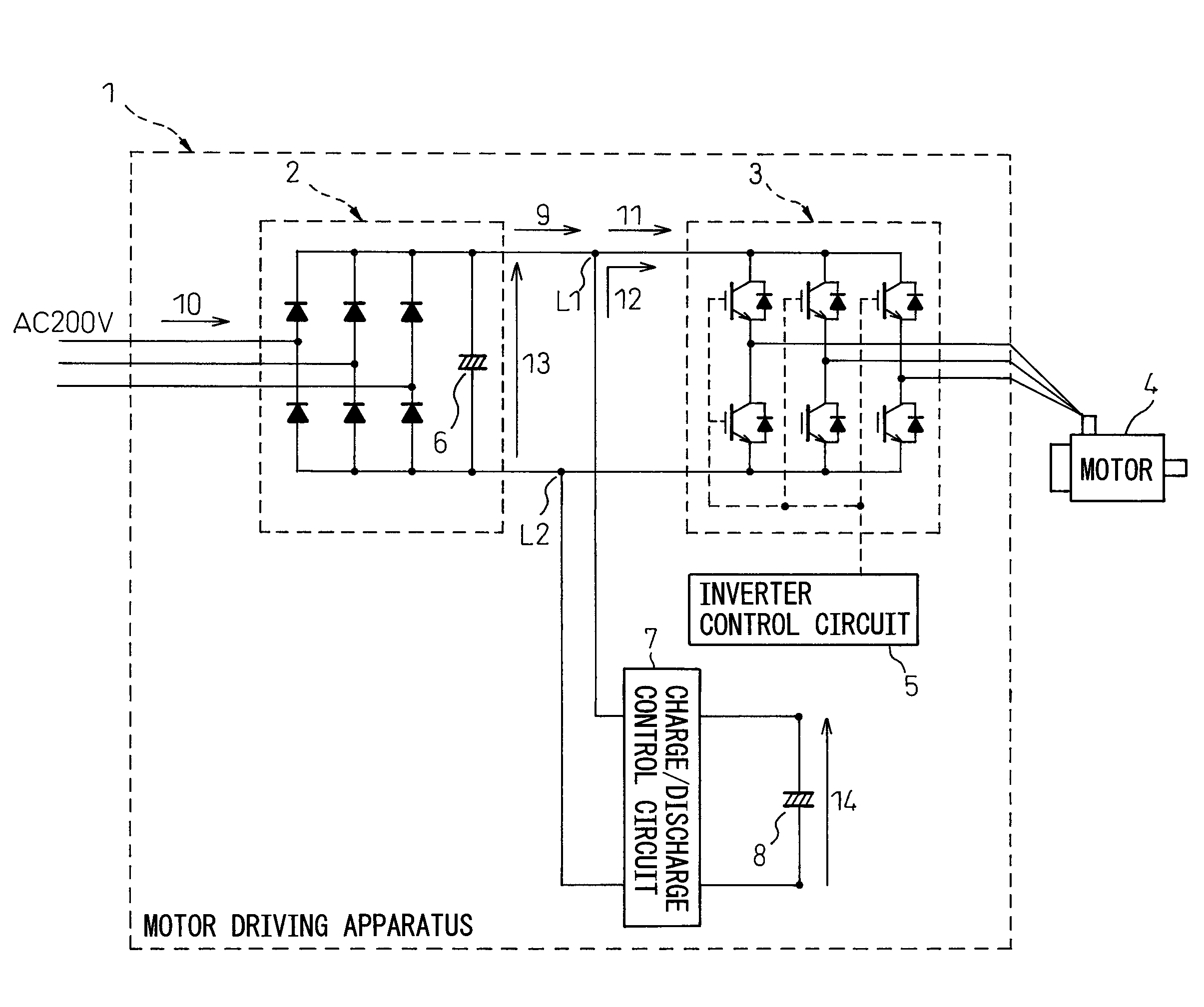
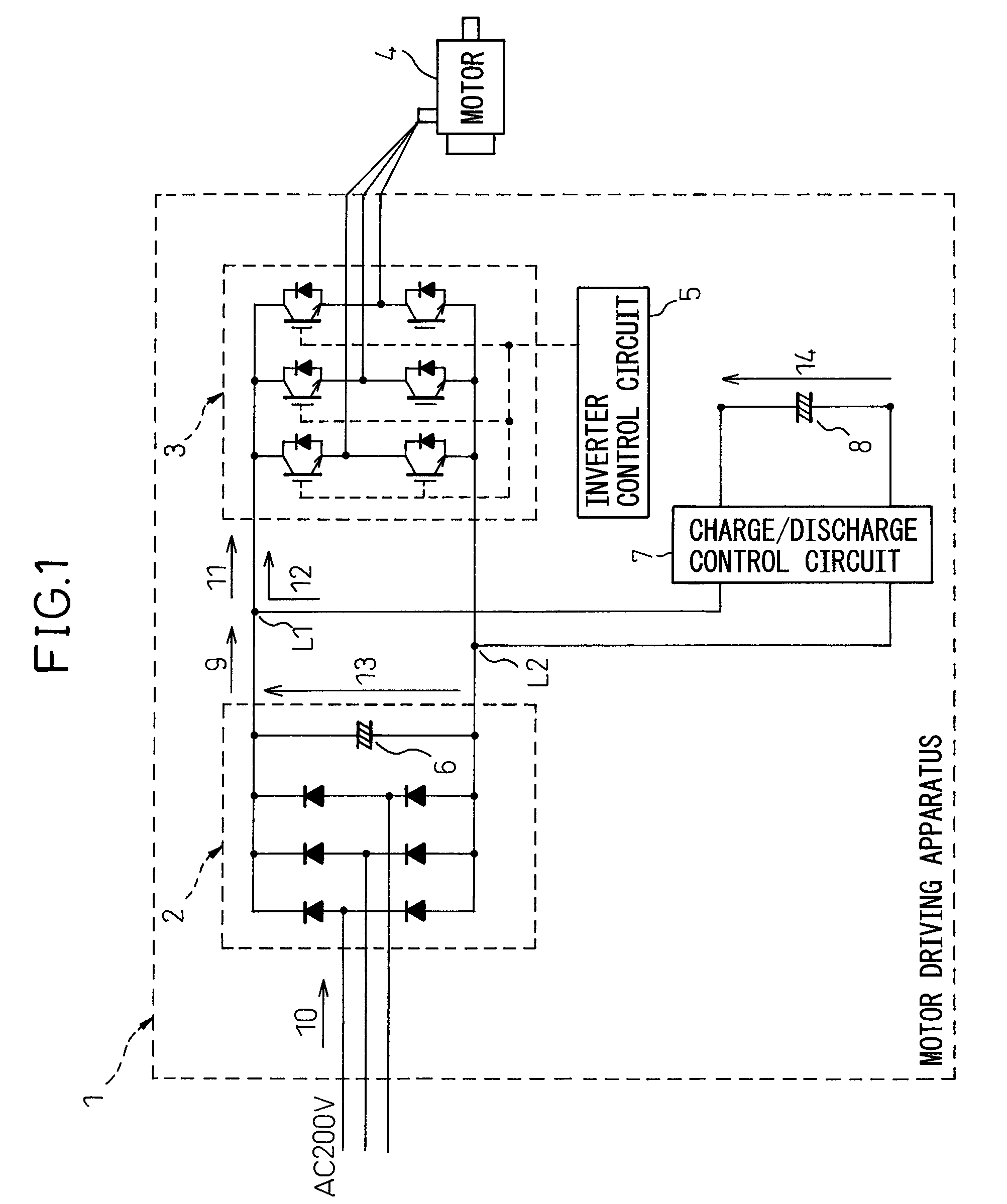
[0054]FIG. 2 is a detailed diagram of the charge / discharge control circuit 7 shown in FIG. 1.

[0055]The regenerative energy is stored via the following route:

[0056]Diode D1→Switch Q1→Capacitor C8

[0057]The energy is supplied (the regenerative energy is discharged) via the following route:

[0058]Capacitor C8→Switch Q2→Reactor L→Diode D2→DC link

[0059]In FIG. 2, Q1 and Q2 may be IGBTs or the like.

[0060](Description of Regenerative Energy Storing)

[0061]When the motor 4 begins to decelerate, the regenerative energy is recovered and stored in the capacitor C8 via the diode D1 and switch Q1 in the energy charge / discharge control circuit 7. Power conversion, etc. are not performed on the regenerative energy.

[0062](Description of Energy Supply / Regenerative Energy Discharging)

[0063]When the motor 4 begins to accelerate, the switch Q2 in the energy charge / discharge control circuit 7 is turned on (or switched on and off) with the timing arbitrarily chosen to supply the energy stored in the capacit...

second embodiment

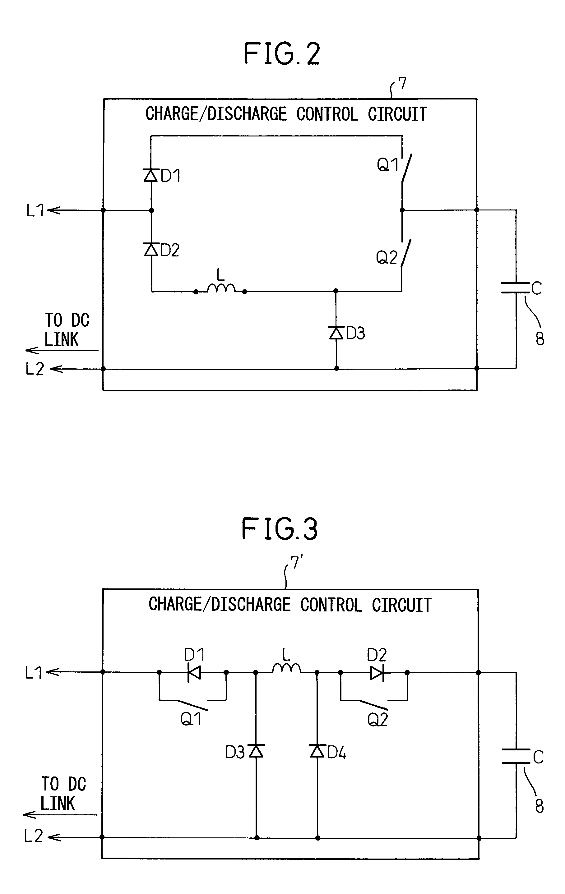
[0065]FIG. 3 is a detailed diagram of the charge / discharge control circuit 7 shown in FIG. 1.

[0066]The regenerative energy is stored via the following route:

[0067]Switch Q1→Reactor L→Diode D2→Capacitor C

[0068]The energy is supplied (the regenerative energy is discharged) via the following route:

[0069]Capacitor C8→Switch Q2→Reactor L→Diode D1→DC link

[0070]In FIG. 3, Q1 and Q2 may be IGBTs.

[0071](Description of Regenerative Energy Storing)

[0072]When the motor 4 begins to decelerate, the regenerative energy is recovered and stored in the capacitor C8 via the switch Q1, reactor L, and diode D2 in the energy charge / discharge control circuit 7′. Power conversion, etc. are not performed on the regenerative energy.

[0073](Description of Energy Supply / Regenerative Energy Discharging)

[0074]When the motor 4 begins to accelerate, the switch Q2 in the energy charge / discharge control circuit 7′ is turned on (or switched on and off) with the timing arbitrarily chosen to supply the energy stored in ...

third embodiment

[0076]FIG. 4 is a detailed diagram of the charge / discharge control circuit 7″ shown in FIG. 1.

[0077]The input current or output current of the converter 2 is monitored by a current sensor or the like not shown, and when the current becomes equal to or exceeds a predetermined current value, the switch Q2 in the charge / discharge control circuit 7 of the first embodiment shown in FIG. 2 or the charge / discharge control circuit 7′ of the second embodiment shown in FIG. 3 is turned on. By monitoring the current in this way, it is determined whether the need has arisen to supply particularly large energy in the second half period of acceleration of the motor 4.

[0078]Next, referring to FIG. 4, an example will be described below in which a determination as to whether the need has arisen to supply particularly large energy in the second half period of acceleration of the motor 4 is made by monitoring a voltage. The voltage developed between the links L1 and L2 connecting the converter 2 and i...


PUM


Abstract

A motor driving apparatus having a converter, which receives AC voltage and converts it to DC power, and an inverter, which receives the DC power and converts it to AC power, includes a charge / discharge control circuit and a capacitor connected in parallel to a link section between the converter and the inverter, and energy stored in the capacitor C8 is charged and discharged at arbitrary timing by the charge / discharge control circuit. The invention thus provides a motor driving apparatus that supplies energy to a motor so that the peak of the input current from a power supply to the motor can also be suppressed when particularly large energy is needed during the second half period of motor acceleration.

Description

RELATED APPLICATIONS[0001]The present application is based on, and claims priority from, Japanese Application Number 2007-262464, filed Oct. 5, 2007, the disclosure of which is hereby incorporated by reference herein in its entirety.BACKGROUND OF THE INVENTION[0002]1. Field of the Invention[0003]The present invention relates to a motor driving apparatus, and more particularly to a motor driving apparatus that stores regenerative energy recovered during motor deceleration into a capacitor and that uses the recovered energy as powering energy during motor acceleration.[0004]2. Description of the Related Art[0005][Background Art][0006]FIG. 13 is a circuit diagram of a motor driving apparatus according to the prior art. The motor driving apparatus 101 shown in FIG. 13 includes a converter 2, an inverter 3, a motor 4, an inverter control circuit 5, and a smoothing capacitor 6. In FIG. 13, reference numeral 109 indicates a converter output current, 110 a converter input current, 111 a DC ...

Claims


Application Information

Patent Timeline
Patent Type & Authority Patents(United States)
IPC IPC(8): H02P1/00
CPCH02M5/458H02P27/08H02J7/345
Inventor MATSUBARA, SHUNSUKEIWASHITA, YASUSUKEYAMADA, YUUICHIHANYU, SHIGEKISHIROUZU, MASATOMOSAKAI, KOUJIROU
Owner FANUC LTD
Why Eureka
Try Eureka