Interactive orthopaedic biomechanics system

a biomechanics and orthopaedic technology, applied in the field of biomechanical and other medical studies, can solve the problems of many permutations of fractures, many challenges in dealing with fractures, plate and locked or unlocked screws, and inability to evaluate or optimize among multiple permutations, so as to reduce one or more of stress and motion

Active Publication Date: 2011-11-08
SMITH & NEPHEW INC
View PDF49 Cites 68 Cited by
  • Summary
  • Abstract
  • Description
  • Claims
  • Application Information

AI Technical Summary

Benefits of technology

Another embodiment of the invention involves a method for using a computer to evaluate one or more options for associating at least one surgical device with a bone. A standard computer may be used and will typically include processing functionality, memory functionality, input functionality and output functionality. The computer accepts a plurality of information elements as input. An information element may be any piece of information or data that is stored in any suitable data format, e.g., in a database record, a file, a message, etc. The method involves (a) inputting at least one first information element into the computer concerning the bone, (b) inputting at least one second information element into the computer concerning the surgical device, (c) inputting at least one third information element into the computer concerning a scenario for associating the surgical device with the bone, (d) using the computer, analyzing the first, second and third information elements, (e) using the computer, outputting at least one fourth information element predicting at least one performance characteristic of the scenario, and (f) using the fourth information element to evaluate whether to follow the scenario to associate the surgical device with the bone or to otherwise evaluate and / or record the biomechanical construct. The first information element may further concern a fracture in the bone, information about the fracture that is rendered on a computer image of a bone, the side of the bone the fracture is on, the type of fracture, and / or the bone condition, among other things. The second information element may further concern the type of the device, the position of the device, information about the selection of at least one screw for use in a hole in the device, and / or information about the characteristics of a screw for use in a hole in the device. Inputting the second information element may further comprise displaying a plurality of holes on a graphical image of the device affixed to the bone and selecting a hole on the image of the device for a screw. The method may further involve optimizing screw configuration by running iterations to minimize one or more of stress and motion.
In some embodiments, one or more of the information elements may be inputted using interactive screens or menus displayed by the computing device. The data for input may be gathered in any suitable or desirable manner, including, but not limited to, digital or non-digital x-ray technology, fluoroscopy technology, computer assisted surgical navigation technology, measuring devices, databases, kinetic evaluation, or other types of evaluation. In some embodiments, the computer may communicate with the device or systems used to gather the data, eliminating the need for the user to input the data. Rather, the systems may, in some embodiments, automatically enter or input the data.

Problems solved by technology

In short, selection of an appropriate medical device may be limited by a surgeon's limited ability to predict the performance of potential fracture and medical device constructs.
However, there are many challenges in dealing with the many permutations of fracture, plate, and locked or unlocked screws.
Biomechanics studies defining the biomechanics for a particular fracture / plate construct typically provide information only for the particular fracture / plate constructs and do not provide any ability to evaluate or optimize among multiple permutations of fracture type and constructs.
However, the approach does not include the actual bone or fracture(s) in the bone in the characterization.

Method used


Image

  • Interactive orthopaedic biomechanics system
  • Interactive orthopaedic biomechanics system
  • Interactive orthopaedic biomechanics system

Examples


Embodiment Construction

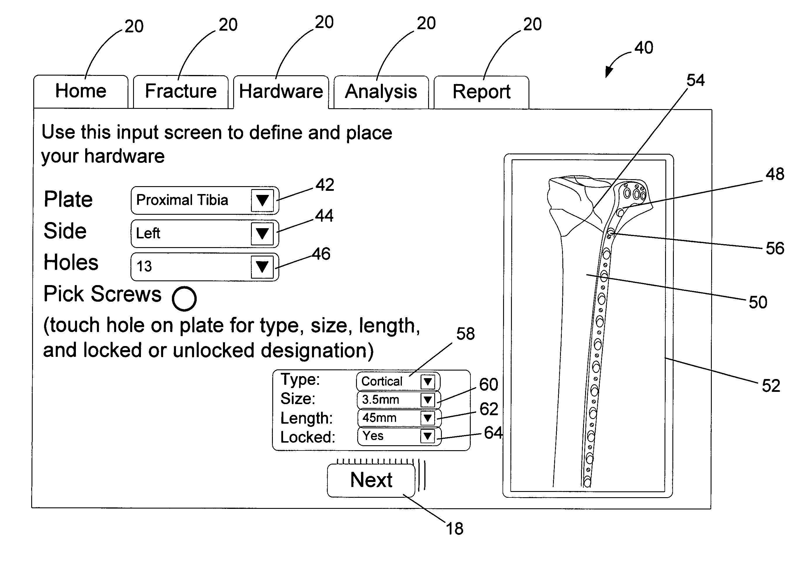
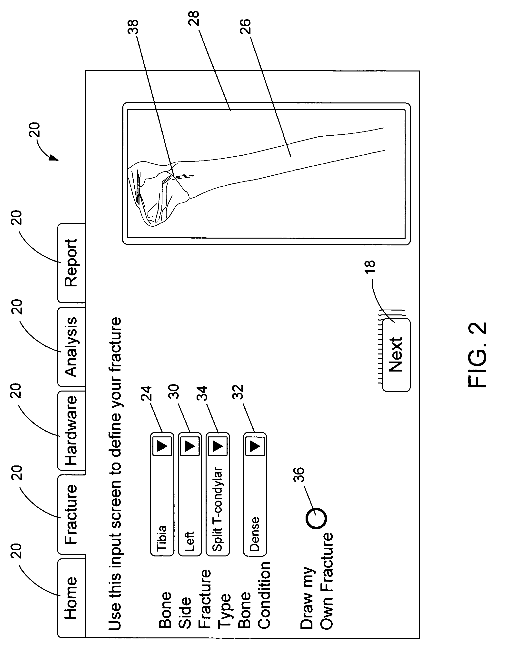
One embodiment of the present invention provides a computer or website that allows a user to load images of a fractured bone and specify a particular configuration of fixation and compression screws with a plate on the loaded bone. The computer is able to replicate normal stresses imposed on the bone by regular activities using finite element analysis. The loaded images may originate from radiographs of the actual fractured bone or may be a predefined bone structure already stored. In one embodiment, the computer is also able to predict which combination of screws will work best. This approach can be applied to any bone / device construct including nails, external fixators, and other products. Also, this system can be developed as a web based system using advanced software analysis tools or as a stand alone system that is programmed for the specific application.

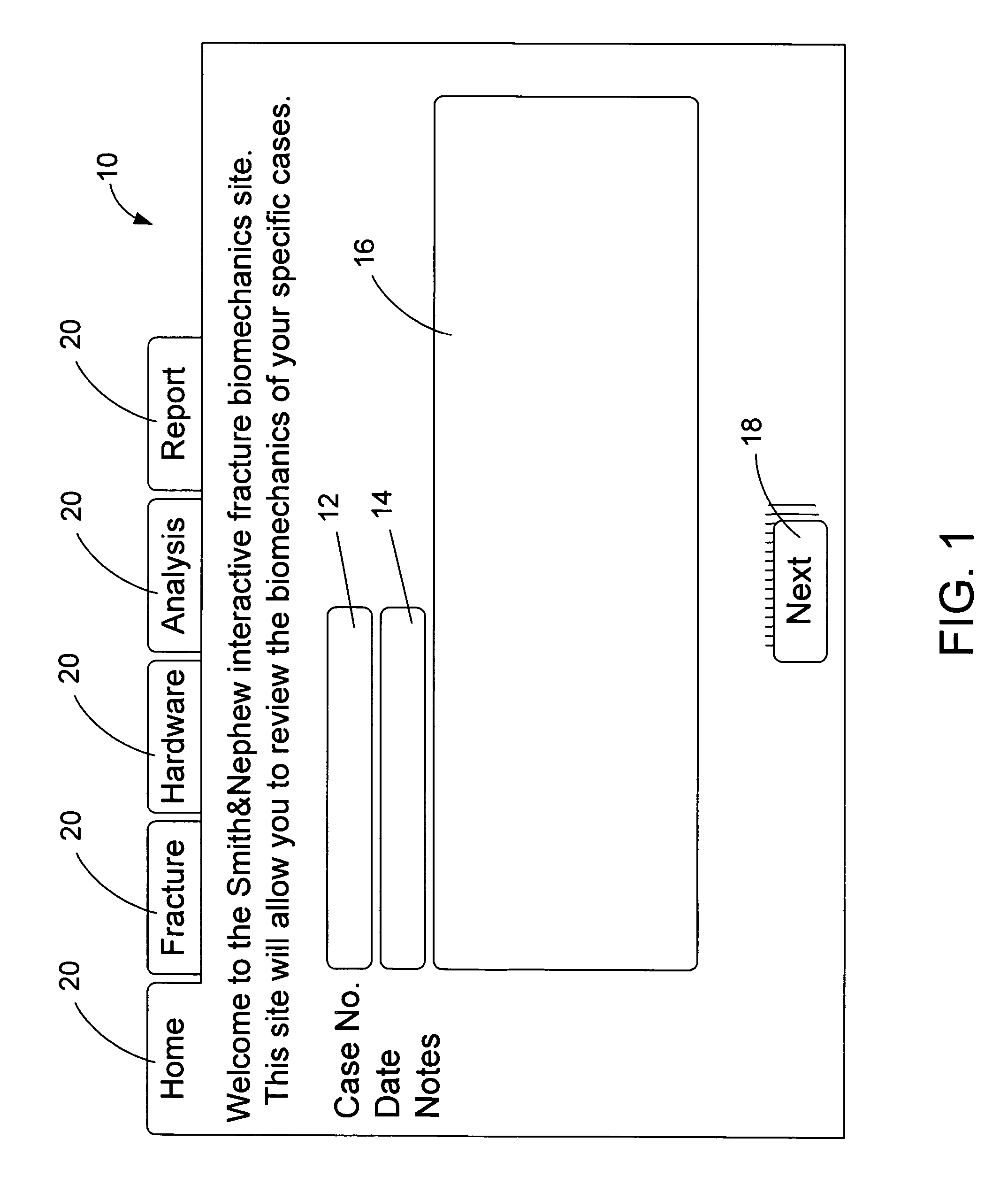
In certain embodiments, the system allows a surgeon or other person to access a website and input information about a patient...


PUM


Abstract

Methods of selecting a configuration of fixation and compression screws for a bone plate to be installed on a bone of a patient. A computer or website allows a user to load images of a fractured bone and specify a particular configuration of fixation and compression screws with a plate on the loaded bone. The computer replicates stresses imposed on the bone by regular activities using finite element analysis and provide information about the suitability of the selected configuration.

Description

FIELD OF THE INVENTIONThe present invention relates generally to biomechanical and other medical studies. More specifically, the present invention relates to computer systems that provide information on, simulate, and / or model possible permutations of fracture types and medical device constructs.BACKGROUNDBone fractures, deformities and other conditions may be treated using a variety of medical devices. A surgeon selecting an appropriate medical device or devices for treatment of a fracture may take into account information about the fracture, the potential devices, the individual patient, and / or the potential stresses and motions to which the bone and device may be subject, among other things. In the case of plates used to treat bone fractures, in order to treat a fracture appropriately, surgeons and others desire to know or predict the proper plate / screw configuration to optimize the biomechanics of the particular fracture they are treating. They also frequently need to select bet...

Claims


Application Information

Patent Timeline
Patent Type & Authority Patents(United States)
IPC IPC(8): G06G7/48
CPCA61B19/52A61B17/80A61B17/8014A61B17/863A61B19/50A61B34/10A61B90/36
Inventor JAMES, ANTHONY
Owner SMITH & NEPHEW INC
Why Eureka
Try Eureka