Process for production of iodine pentafluoride

a technology of iodine pentafluoride and process, which is applied in the direction of inorganic chemistry, inter-halogen compound, halide preparation methods, etc., can solve the problems of difficult operation of the reactor at an elevated temperature for the purpose of avoiding such iodine deposition, and the industrial value of processes is not so useful, so as to reduce the risk of iodine deposition and solidification in the line

Inactive Publication Date: 2011-11-15
DAIKIN IND LTD
View PDF10 Cites 0 Cited by
  • Summary
  • Abstract
  • Description
  • Claims
  • Application Information

AI Technical Summary

Benefits of technology

[0026]By supplying fluorine to the gas phase according to the production process of iodine pentafluoride of the present invention, fluorine supplied to the gas phase preferentially reacts with iodine present in the gas phase (that is, the reaction (a) occurs), and residual fluorine if any approaches to the liquid phase or gets into the liquid phase so that it reacts with dissolved and / or dispersed iodine which is present in iodine pentafluoride as the liquid phase (that is, the reaction (b) and / or reaction (c) occurs). Because of such reaction(s), flowing out of unreacted iodine through a line which discharges a gas from the reactor is suppressed, so that the risk of the deposition and solidification of iodine in the line is reduced.
[0027]Further, flowing back of iodine to the fluorine supply line which is possible in the production process of iodine pentafluoride of the prior art as well as the problems related to such flowing back can be avoided back due to the fluorine supply to the gas phase. It is noted that the conversion of fluorine supplied to gas phase in the production process of iodine pentafluoride according to the present invention depends on operation conditions. The production process according to the present invention is operated such that the fluorine conversion reaches generally not smaller than 75%, preferably not smaller than 85%, more preferably not smaller than 90%, and particularly preferably not smaller than 95%, for example not smaller than 98% or more by properly selecting the operation conditions (for example, a reaction pressure, a reaction temperature, an amount of supplied fluorine, an extent of stirring if necessary, and an amount of coexistent hydrogen fluoride which will be explained below.

Problems solved by technology

As a result, iodine deposits and becomes solid onto an inside of an outlet line of a reactor, which ultimately may lead to clogging of the line.
An operation of the reactor at an elevated temperature for the purpose of avoiding such iodine deposition is difficult.
Thus, those processes are industrially not so useful from a viewpoint of the safety.
When fluorine becomes in contact with concentrated iodine such as the slurry iodine, or the molten iodine, there is a risk in that they react explosively, so that there leads to a risk in that iodine flows back to a fluorine supply line.
If fluorine goes back to its supply line, fluorine and iodine reacts in such line, and the temperature in the line is locally and rapidly increased, which leads to a risk in that the line, an apparatus related thereto and the like are damaged.
Particularly, with reaction heat removal by means of sensible heat using an indirect heat exchanger (such as an outside jacket) which is conventionally used for the removal of the reaction heat in a reactor, an amount of heat which can be effectively removed is too small compared with the heat formed by the reaction, so that control of the reaction temperature is difficult.
Upon scale-up of the reactor, there is a risk in that runway of the reaction, and further explosion may occur.
Further, since there is a risk in that line clogging by means of sublime iodine, this process is not necessarily satisfactory for the industrial process.Patent Reference 1: U.S. Pat. No. 3,367,745Patent Reference 2: Japanese Patent Kokai Publication No. 65196 / 1979Patent Reference 3: G.B. Patent No. 1326130Patent Reference 4: Japanese Patent Kokai Publication No. 145602 / 1983

Method used


Image

  • Process for production of iodine pentafluoride
  • Process for production of iodine pentafluoride

Examples


example 1

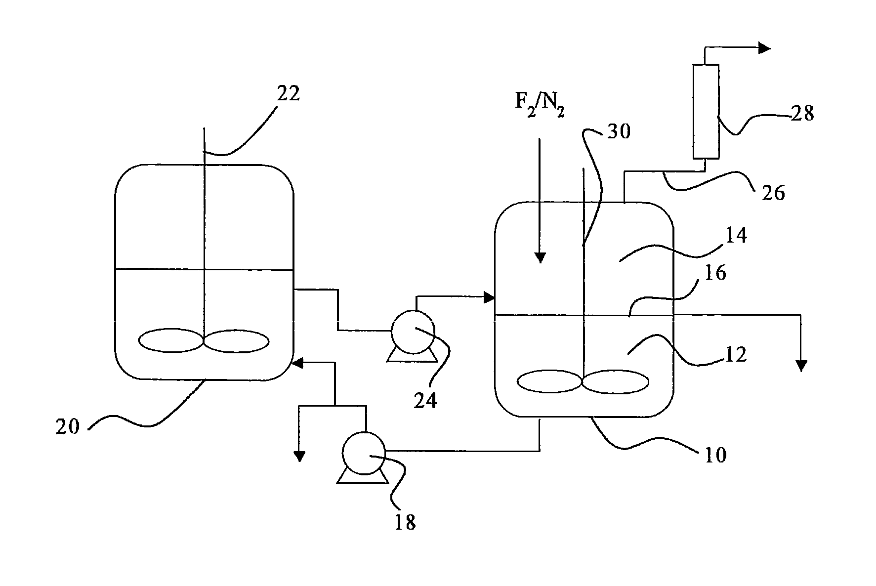
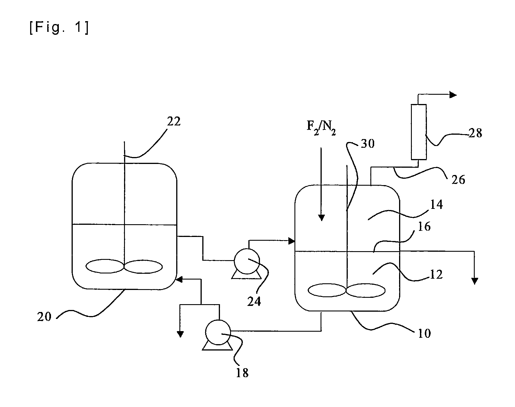
[0058]Iodine (40 g) and iodine pentafluoride (223 g) were charged in a reactor made of a fluorine resin (PFA) having an inner volume of 150 ml, and stirred so as to prepare a liquid phase in the state of a slurry. Fluorine and nitrogen were supplied to the gas phase of the reactor at flow rates of 50 Ncc / min. and 50 Ncc / min., respectively. The reaction of iodine and fluorine was started while an inside temperature of the reactor was kept at a temperature in the range between 30 and 50° C. by cooling the reactor in an ice bath. The reaction was continued for six hours, and no back stream of iodine into the nitrogen line or the fluorine line was observed, so that the reaction proceeded smoothly. Noncondensed gas discharged from the reactor was analyzed by a ultraviolet-visible spectrophotometer, and it was found that a conversion of fluorine was 98 mol %. The liquid phase in the reactor was composed substantially of iodine pentafluoride, and iodine disappeared.

example 2

[0060]Iodine (75 g) and iodine pentafluoride (300 g) were charged and stirred in an autoclave made of a metal (SUS 316) having an inner volume of 200 ml, so that a liquid phase in the state of a slurry was prepared. A mixture gas of fluorine (90 Ncc / min.) and nitrogen (10 Ncc / min.) was supplied to the gas phase of the autoclave, and the reaction of iodine and fluorine was started with stirring at a rotation speed of 500 r.p.m. while an inside temperature of the autoclave was kept at a temperature in the range between 30 and 50° C. by cooling the autoclave in an ice bath. The reaction was continued for seven hours, and no back stream of iodine into the nitrogen / fluorine line was observed, so that the reaction proceeded smoothly. The liquid phase left in the reactor was recovered, all of iodine in the reactor was consumed, and the iodine was absent, and the liquid phase was a transparent and colorless liquid. The liquid was analyzed by 19F-NMR, and it was found that it contained 100 m...

example 3

[0061]A liquid phase of a slurry was prepared in an autoclave made of a metal (SUS 316) having an inner volume of 200 ml as in Example 2. A mixture gas of fluorine (180 Ncc / min.) and nitrogen (20 Ncc / min.) was supplied to the gas phase of the autoclave, and the reaction of iodine and fluorine was started with stirring at a rotation speed of 500 r.p.m. while an inside temperature of the autoclave was kept at a temperature in the range between 30 and 50° C. by cooling the autoclave in an ice bath. The reaction was continued for three hours, and no back stream of iodine into the nitrogen / fluorine line was observed, so that the reaction proceeded smoothly. Noncondensed gas discharged from the autoclave was analyzed by a ultraviolet-visible spectrophotometer, and it was found that a conversion of fluorine was always not smaller than 98%. After the reaction, the charged iodine was not completely consumed, and an amount of iodine was left in the autoclave, and there was no deposition of so...


PUM

PropertyMeasurementUnit
temperatureaaaaaaaaaa

Abstract

There is provided a process for the production of iodine pentafluoride which avoids the problems of the production process of iodine pentafluoride of the prior art as much as possible, and which carries out the reaction of fluorine and iodine moderately, so that iodine pentafluoride is produced more safely and more productively. In the process for the production of iodine pentafluoride by reacting fluorine and iodine, fluorine is supplied to the gas phase 14 which is adjacent to the liquid phase 12 of iodine pentafluoride which contains iodine.

Description

TECHNICAL FIELD[0001]The present invention relates to a process for the production of iodine pentafluoride (IF5) by reacting iodine and fluorine. Iodine pentafluoride is useful as a raw material for the production of an intermediate of a reactive fluorinating agent or a fluorine-containing compound.BACKGROUND ART[0002]As a process for the production of iodine pentafluoride by reacting iodine and fluorine, the followings are exemplified: A counter current contacting process of fluorine with iodine dissolved in iodine pentafluoride (see Patent Reference 1); and a bubbling process of fluorine into molten iodine or slurry iodine (see Patent References 2 and 3).[0003]In the above processes, fluorine is supplied to a liquid phase, and sublimation of iodine is accelerated by nitrogen used as a diluting gas for the fluorine supply, unreacted fluorine and the like. As a result, iodine deposits and becomes solid onto an inside of an outlet line of a reactor, which ultimately may lead to clogg...

Claims


Application Information

Patent Timeline
Patent Type & Authority Patents(United States)
IPC IPC(8): C01B7/24
CPCC01B7/24
Inventor YOSHIMI, HITOSHIHIRATA, TATSUYAISOGAI, TOMOHIROSHIBANUMA, TAKASHI
Owner DAIKIN IND LTD
Why Eureka
Try Eureka