MRI-monitored equipment with built-in MR signal reception coil and signal emitter

a technology of mrimonitored equipment and signal emitters, which is applied in the field of magnetic resonance imaging, can solve the problems of less ideal imaging quality, low signal-to-noise ratio during imaging by such a large body coil, and achieve the effect of improving the compatibility between the mri system and the guided medical equipment, improving the surgical operation effect of therapeutic equipment, and improving the quality

Active Publication Date: 2011-11-15
SIEMENS HEALTHCARE GMBH
View PDF3 Cites 30 Cited by
  • Summary
  • Abstract
  • Description
  • Claims
  • Application Information

AI Technical Summary

Benefits of technology

[0013]An advantage of the present invention is that the compatibility between the MRI system and the medical equipment guided is significantly improved, and the MRI real time detection during a treatment becomes more convenient. The drawbacks in the sealing and fixing of the previous coil and the cable are avoided, and images of a better quality are provided during therapy. Therefore, surgical operation effects of therapeutic equipment, particularly the HIFU equipment, are improved. Furthermore, the present invention is convenient to install, easy to maintain, and the imaging quality and flexibility are improved by the coils of various sizes for detecting corresponding positions, and the simple mechanical devices also reduce malfunction rate.
is that the compatibility between the MRI system and the medical equipment guided is significantly improved, and the MRI real time detection during a treatment becomes more convenient. The drawbacks in the sealing and fixing of the previous coil and the cable are avoided, and images of a better quality are provided during therapy. Therefore, surgical operation effects of therapeutic equipment, particularly the HIFU equipment, are improved. Furthermore, the present invention is convenient to install, easy to maintain, and the imaging quality and flexibility are improved by the coils of various sizes for detecting corresponding positions, and the simple mechanical devices also reduce malfunction rate.

Problems solved by technology

However, there are always some problems when such medical equipment is used in conjunction with an MRI system.
When using medical equipment such as HIFU which requires very high precision imaging, the signal-to-noise ratio during the imaging by such a large body coil does not meet the requirements (the imaging quality of the body coil is not very high due to the fact that the coil is too large, and the bigger the coil is, the less ideal is the imaging quality).
Therefore the local imaging quality is not high.
An alternative is to acquire the magnetic resonance signals using a fixed receiving coil (local coil), but there are many restrictions in practical application.
Since a fixed coil needs to be placed in HIFU solution in order to receive the magnetic resonance signals emitted from the body, and the fixed coil also needs to be connected to a cable and to transmit the magnetic resonance signals to the MRI processor for imaging, there is the problem of sealing the coil and the cable.
Moreover, the need to seal the cable and the fixed coil in turn creates the problem of inconveniency in moving the fixed coil, which further results in a restriction to imaging range.
All these problems are difficulties encountered when using the fixed coil.

Method used


Image

  • MRI-monitored equipment with built-in MR signal reception coil and signal emitter
  • MRI-monitored equipment with built-in MR signal reception coil and signal emitter

Examples


Embodiment Construction

[0017]The present invention is described in detail with reference to the accompanying drawings.

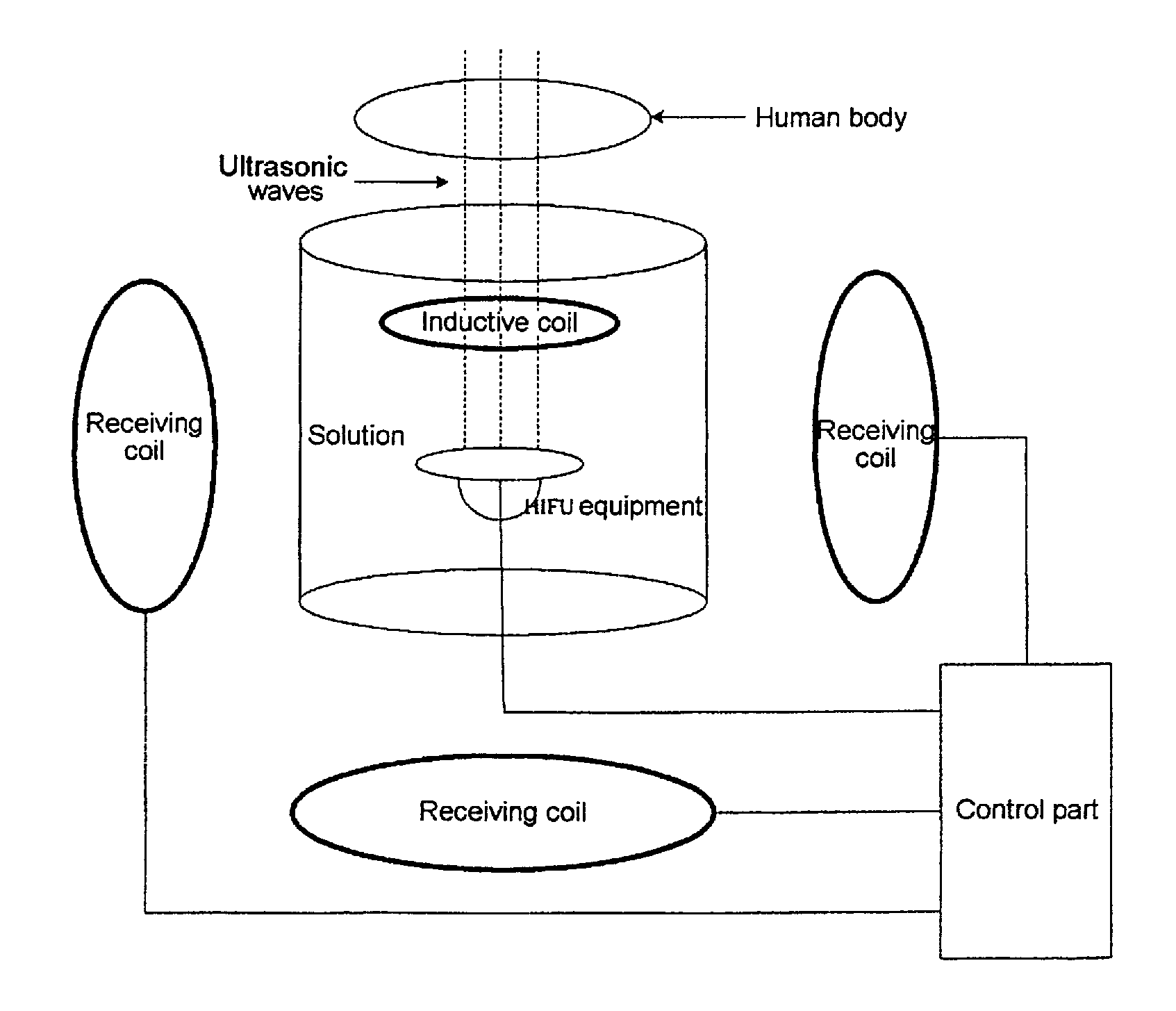
[0018]When magnetic resonance signals are received by using a fixed coil in the current MRI-monitored medical equipment, the coil may need to be sealed or be moved flexibly, at such time an inductive coupling coil can be used to achieve the functions of a fixed coil, and hereinbelow, the detailed construction of the present invention is described with an MRI system-guided HIFU equipment as an example.

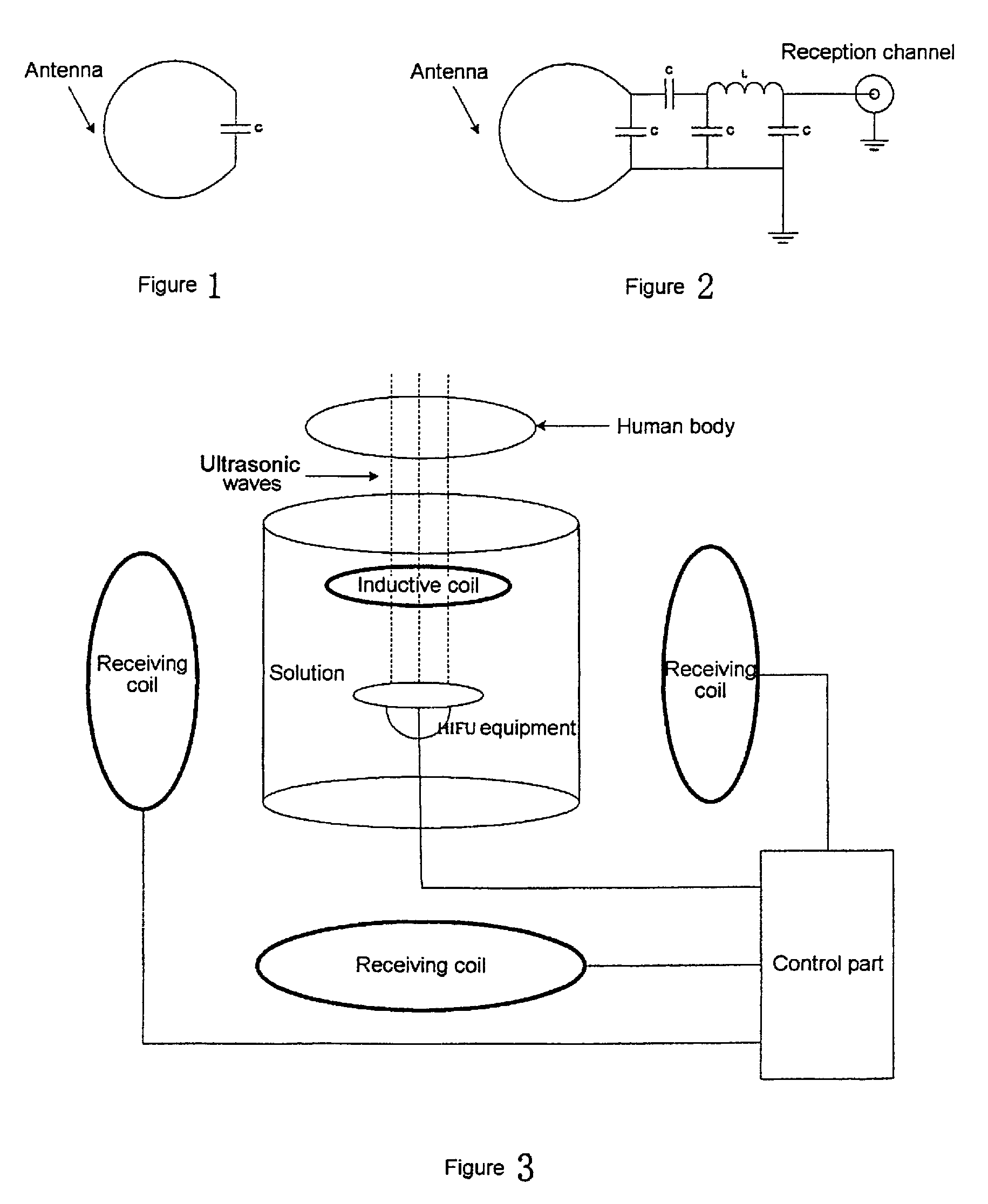
[0019]An inductive coupling coil is divided into two parts: an inductive coil (shown in FIG. 1) is a standard LC resonance coil for receiving magnetic resonance signals returning from a human body and generating corresponding inductive electromagnetic waves. The receiving coil is a common coil (shown in FIG. 2) for receiving the electromagnetic wave signals from the inductive coil and transmitting the same to the MRI system via a signal channel. The inductive coil is relatively independent, an...


PUM


Abstract

In a system having a magnetic resonance imaging (MRI) apparatus and MRI-monitored medical equipment, the MRI-monitored medical equipment has an inductive coil built into the equipment that receives magnetic resonance signals from a subject and generates inductive electromagnetic signals according to the received magnetic resonance signals. The magnetic resonance imaging system has at least one reception coil that is positioned externally of the MRI-monitored medical equipment and that is connected to the magnetic resonance imaging system via a cable. The reception coil receives the electromagnetic signals that are generated by the inductive coil that is built into the medical equipment.

Description

BACKGROUND OF THE INVENTION[0001]1. Field of the Invention[0002]The present invention relates to the field of magnetic resonance, particularly to the field of magnetic resonance imaging, and specifically, to an apparatus for transmitting magnetic resonance signals in MRI-monitored medical equipment.[0003]2. Description of the Prior Art[0004]Various forms of therapeutic treatments can be applied to the body of a human or other mammalian subject by applying energy from outside the body. For example, when treatments are performed by using hyperthermia techniques, ultrasonic or radio frequency energy is applied externally to a subject's body to heat different tissues. This is known as the high intensity focused ultrasonic knife (HIFU) technique. The working principle of the technique is that high-energy ultrasonic waves are emitted without contact and enter a human body via a water medium coupling. The applied energy can be focused to a very small spot within the human body so as to hea...

Claims


Application Information

Patent Timeline
Patent Type & Authority Patents(United States)
IPC IPC(8): A61B5/055
CPCA61B5/055A61B6/462G01R33/3642G01R33/4814
Inventor HE, ZENG HEWANG, JIAN MINWANG, YANG
Owner SIEMENS HEALTHCARE GMBH
Why Eureka
Try Eureka