Magnetic recording disk and method for manufacture thereof

a recording disk and magnetic technology, applied in the field of magnetic recording disks, can solve the problems of inability to specify lubricant molecular structure and quantitative data, weight-average molecular weight or number-average molecular weight is not effective in precisely evaluating the properties of lubricants, etc., to achieve high reliability, reduce the flying height of the magnetic head, and high heat resistance

Inactive Publication Date: 2011-11-22
WD MEDIA SINGAPORE PTE
View PDF7 Cites 73 Cited by
  • Summary
  • Abstract
  • Description
  • Claims
  • Application Information

AI Technical Summary

Benefits of technology

[0027]According to the present invention, terminal groups of perfluoropolyether compounds contained in a lubricant are specified in terms of structure and quantitative data; hence, properties of the lubricant can be clearly specified. According to the present invention, a lubricant which has high heat resistance and in which migration causing fly stiction hardly occurs can be specified. Accordingly, the present invention can provide a magnetic recording disk that exhibits high reliability even if the flying height of a magnetic head is reduced.

Problems solved by technology

There is, however, a problem in that weight-average molecular weight or number-average molecular weight is not effective in precisely evaluating properties of lubricants, particularly whether the migration of the lubricants that causes fly stiction occurs, because weight-average molecular weight or number-average molecular weight does not specify the composition of each lubricant.
However, if a lubricating layer is analyzed by a conventional technique, for example, nuclear magnetic resonance spectroscopy, there is a problem in that a peak originating from a methylene group (—CH2—) overlaps with a peak originating from a hydroxyl group (—OH) as shown in FIG. 3 and therefore the lubricant cannot be specified in terms of both molecular structure and quantitative data.

Method used


Image

  • Magnetic recording disk and method for manufacture thereof
  • Magnetic recording disk and method for manufacture thereof
  • Magnetic recording disk and method for manufacture thereof

Examples


Embodiment Construction

[0036]Embodiments of the present invention will now be described with reference to the accompanying drawings.

[0037](Configuration of Magnetic Recording Disk)

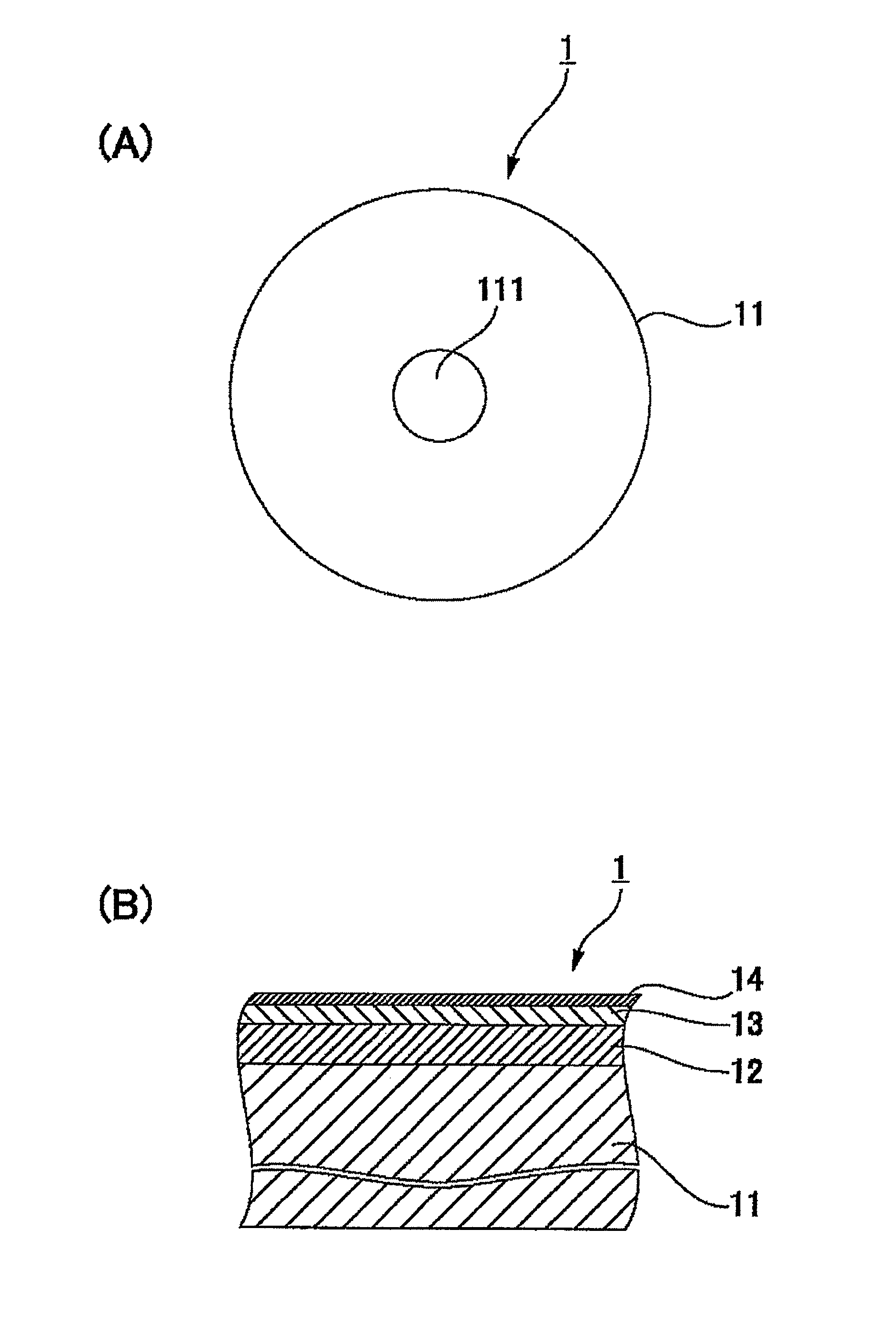
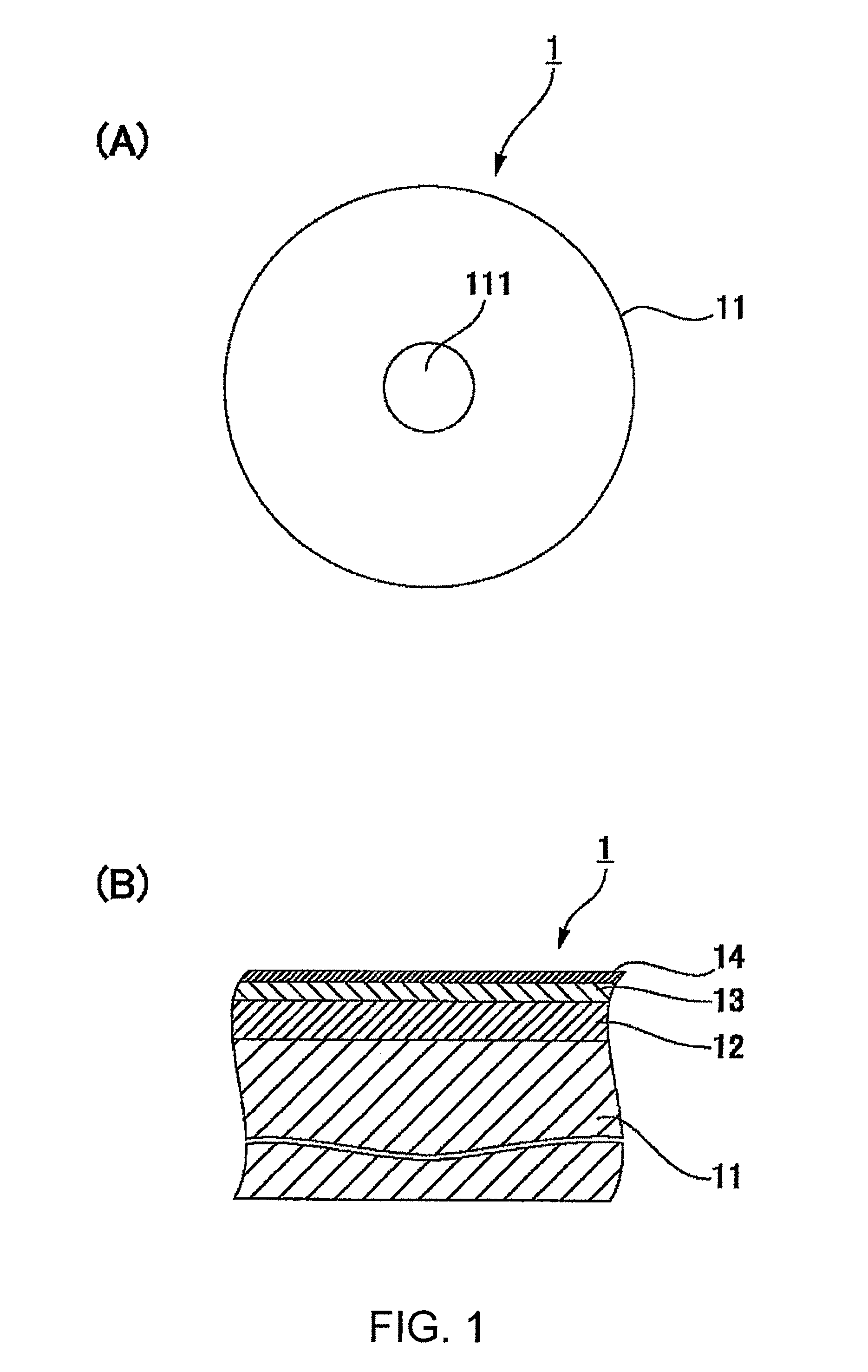
[0038]FIG. 1(A) is a plan view of a magnetic recording disk according to an embodiment of the present invention and FIG. 1(B) is a schematic sectional view of the magnetic recording disk. With reference to these figures, the magnetic recording disk 1 includes a circular nonmagnetic substrate 11 having a center hole 111, a base layer (not shown), a magnetic layer 12 formed by a DC magnetron sputtering process, a protective layer 13 formed by a plasma-enhanced CVD process, and a lubricating layer 14 formed by a dipping process, these layers being arranged on the nonmagnetic substrate 11 in that order. The nonmagnetic substrate 11 is made of, for example, chemically reinforced glass such as aluminosilicate glass. The protective layer 13 is, for example, 5 nm thick, is made of hydrogenated carbon (diamond-like carbon), and has high ...


PUM

PropertyMeasurementUnit
flying heightaaaaaaaaaa
thickaaaaaaaaaa
thickaaaaaaaaaa

Abstract

In order to obtain a magnetic recording disk that exhibits high reliability even if the flying height of a magnetic head becomes very narrow, a lubricant is specified in terms of both molecular structure and quantitative data. That is, a lubricating layer 14 of the magnetic recording disk 1 is formed by a lubricant which contains perfluoropolyether compounds represented by the following chemical formula (Chemical Formula 1) and which has a first component content of 71.7%, a second component content of 15.7%, a third component content of 11.7%, a fourth component content of 0.3%, and a fifth component content of 0.6%:X—OCH2CF2—(CF2O)m(C2F4O)n—CF2OCH2O—X  (Chemical Formula 1)m, n=9 to 11first component: X=X1=CH2CH(OH)CH2OHsecond component: X=X2=CH2CH(OH)CH2OCH2CH(OH)CH2OHthird component: X=X3=Hfourth component: X=X4=CF3 fifth component: X=X5=CF2Cl.

Description

TECHNICAL FIELD[0001]The present invention relates to a magnetic recording disk and a method for manufacturing the magnetic recording disk. The present invention particularly relates to a material technology for lubricating layers.BACKGROUND ART[0002]Magnetic recording disks each include a nonmagnetic substrate on which at least a magnetic recording layer, a protective layer, and a lubricating layer, are arranged in that order. The lubricating layer has a function of reducing the impact of the magnetic recording disk against a magnetic head. The distance between the magnetic recording disk and the magnetic head becomes narrower and narrower with an increase of a recording capacity of a magnetic recording disk drive such as a HDD. Since a LUL (load / unload) system has been employed, the flying height of the magnetic head is reduced. The magnetic head needs to stably operate at an ultra-low flying height of 10 nm or less.[0003]Under such conditions, the magnetic head may often instanta...

Claims


Application Information

Patent Timeline
Patent Type & Authority Patents(United States)
IPC IPC(8): G11B5/65
CPCC10M107/38G11B5/725G11B5/82G11B5/8408C10N2230/00C10N2230/08C10N2240/204C10N2030/00C10N2030/08C10N2040/18G11B5/7257
Inventor SUZUKI, KOTASHIMOKAWA, KOICHI
Owner WD MEDIA SINGAPORE PTE
Why Eureka
Try Eureka