
Image display system, image display device, and image data output device

a display system and image technology, applied in the field of image display system, image display device, image data output device, can solve the problems of large load on the transmission line or the driving circuit, large load on the main processor at the computer side, and inability to achieve the display based on the frame rate of the moving picture, so as to reduce the amount of image data flowing

Active Publication Date: 2011-11-22
SEIKO EPSON CORP
View PDF9 Cites 9 Cited by
  • Summary
  • Abstract
  • Description
  • Claims
  • Application Information

AI Technical Summary

Benefits of technology

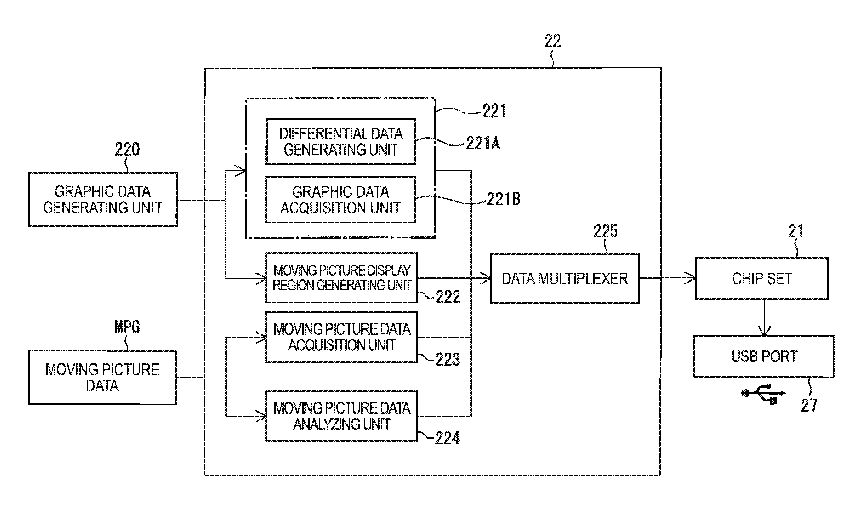
The invention provides an image display system that can display high-quality moving pictures without overloading the image data output device or the image display device. This is achieved by reducing the amount of image data transmitted through a transmission line and by using compressed moving picture data that is decoded and rasterized on the image display device. The system also includes a synchronization signal generating unit that generates an image synchronizing signal for updating a screen of the display raster data generated by the data synthesizing unit. This allows for a high-quality moving picture display without dropping frames or jerky movement. The system also includes an image / audio separating unit that separates audio data from the compressed moving picture data and an audio data decoder that decodes the audio data. The audio output unit outputs the audio data and the audio output synchronization adjusting unit synchronizes the timing of the audio output with the generation time of the moving picture.

Problems solved by technology

In this case, if the raster data of a captured screen is transmitted under the uncompressed state, a large amount of data proportional to display resolution, color depth, and a frame rate flows through a transmission line, which causes a problem in that the load imposed on the transmission line or a driving circuit becomes significantly large.
In addition, even a main processor at the computer side should capture and transmit data corresponding to the entire screen, and accordingly, the load imposed on the main processor at the computer side becomes also large.
In addition, if frame update is not made according to the frame rate of the moving picture, display based on the frame rate of the moving picture is not achieved.
In this case, since a viewer can see dropping frames or jerky movement on the displayed moving picture, it is not possible to secure the quality of a display image.
Furthermore, in the case where the moving picture is compressed moving picture data based on MPEG2 (ISO / IEC 13818-2) or the like, decoding of the moving picture, color conversion, a scaling, and a rasterizing process such as display processing need to be performed at the image data output device side, which also causes a problem in that the load imposed on the image data output device and the transmission line becomes even larger.

Method used


Image

  • Image display system, image display device, and image data output device
  • Image display system, image display device, and image data output device
  • Image display system, image display device, and image data output device

Examples


first embodiment

1. First Embodiment

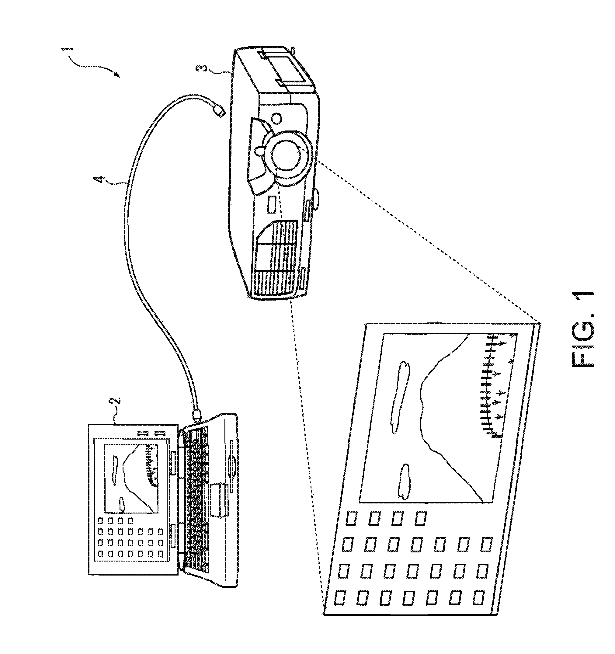
[0040]FIG. 1 illustrates an image display system 1 according to a first embodiment of the invention. The image display system 1 includes a computer 2 serving as an image data output device, a projector 3 serving as an image display device, and a USB cable 4 serving as a transmission line by which the computer 2 and the projector 3 are connected to each other. Image data output from the computer 2 is input to the projector 3 through the USB cable 4, and an image on a local display of the computer 2 can be displayed as a projection image on a screen. The USB cable 4 is a cable based on the specifications, such as USB 1.1 or USB 2.0, and two-way communication between connected devices can be performed through the USB cable 4.

(1) Structure of Computer 2

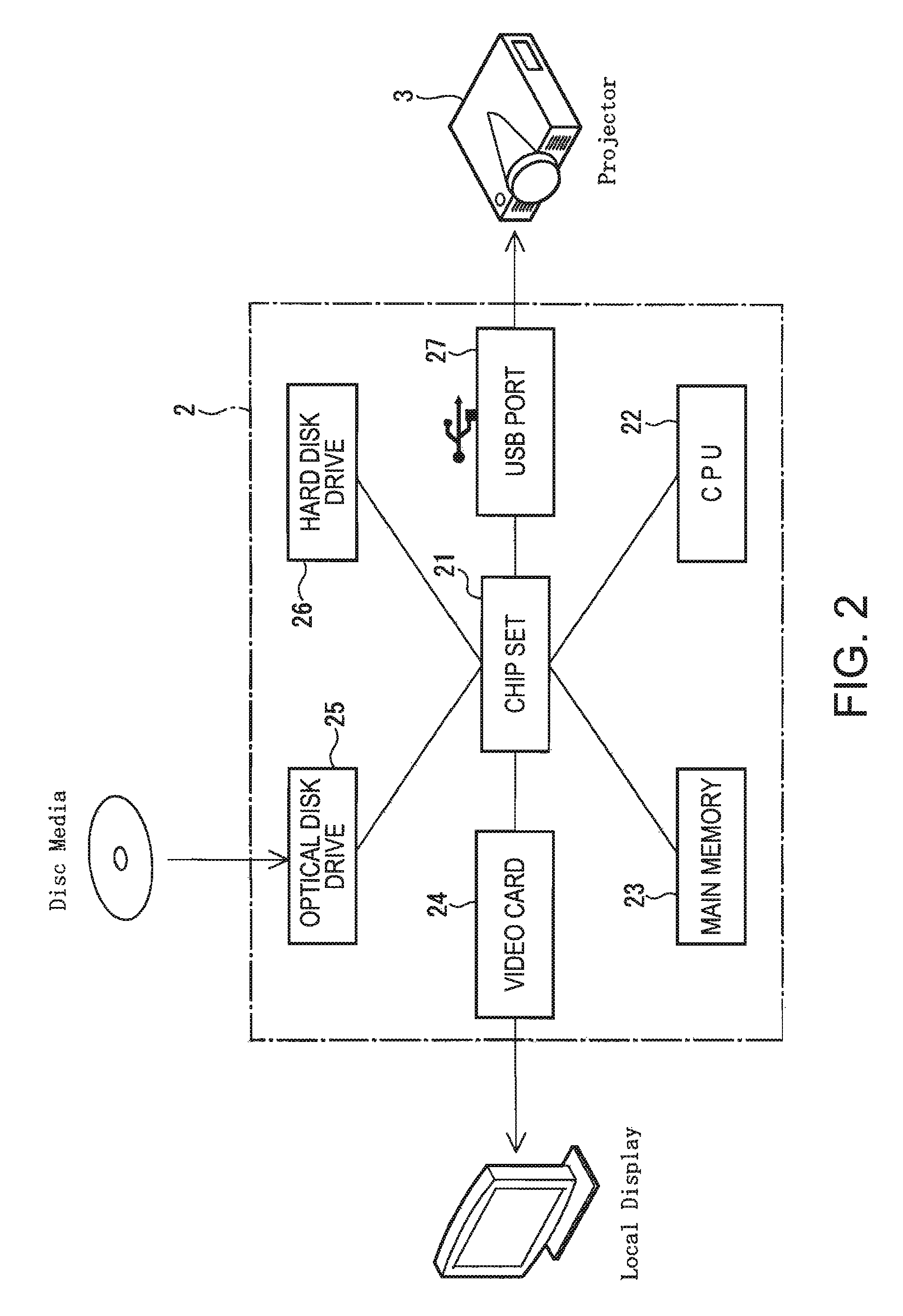
[0041]As shown in FIG. 2, the computer 2 serving as an image data output device includes a chip set 21 provided on a mother board, a CPU 22, a main memory 23, a video card 24, an optical disk drive 25, a hard disk drive...

second embodiment

2. Second Embodiment

[0092]Next, a second embodiment of the invention will be described. In addition, in the following description, the same components as those described above have the same reference numerals, and a detailed description thereof will be omitted.

[0093]In the first embodiment described above, the projector 3 serving as an image display device performs only image display on the basis of the compressed moving picture data output from the computer 2.

[0094]On the other hand, as shown in FIG. 8, an image display system according to the second embodiment is different from that according to the first embodiment in that a projector 7 is provided with a speaker 73 and audio data recorded in synchronization with image data is output from the speaker 73 when compressed moving picture data is decoded.

(1) Configuration of Image / Audio Processing Unit 8

[0095]Specifically, as shown in FIG. 8, the projector 7 according to the second embodiment includes circuit elements for audio output...


PUM


Abstract

An image display system includes: an image data output device that multiplexes and outputs raster data and compressed moving picture data; and an image display device that is connected to the image data output device through a transmission line and displays an image on the basis of image data output from the image data output device. The image display system is capable of displaying a high-quality moving picture on the image display device by reducing the amount of image data flowing through the transmission line without imposing excessive load on the image data output device, the image display device, the image data output device, an image processing program, and a computer-readable recording medium having the image processing program recorded therein.

Description

BACKGROUND[0001]1. Technical Field[0002]The present invention relates to an image display system, an image display device, and an image data output device.[0003]2. Related Art[0004]In recent years, as an image processing function of a computer is highly improved, there is proposed a system in which a computer performs an image processing, which has been performed by an image display device in the related art, image processing data after the processing is transmitted to an image display device side in a digital format, and an image is displayed by the mage display device, such as a projector (for example, refer to JP-A-2004-69990).[0005]In such an image display device, raster data captured by a frame memory of a video output unit of an image data output device, such as a computer, connected to the image display device, is encoded in a predetermined transmission format between the devices and is then transmitted and input to the image display device through a transmission line, such a...

Claims


Application Information

Patent Timeline
Patent Type & Authority Patents(United States)
IPC IPC(8): G09G5/00G06K9/36G03B21/00G09G3/20G09G3/36G09G5/02G09G5/12G09G5/377H04N7/173H04N21/4402
CPCH04N5/4401H04N5/44508H04N21/23614H04N21/2368H04N21/4122H04N21/4131H04N21/4307H04N21/4312H04N21/4314H04N21/434H04N21/4341H04N21/4348H04N21/4402H04N5/74H04N21/426H04N21/43072
Inventor YAMADA, NORIHIKO
Owner SEIKO EPSON CORP
Learn More