Neutron shielding panels for reactor pressure vessels

a technology of neutron shielding and pressure vessel, which is applied in the field of nuclear reactor internals, can solve the problems of vessel fracturing, material embrittlement, and reduced toughness of the vessel, and achieve the effect of reducing the passage of neutron fluen

Active Publication Date: 2011-11-22
WESTINGHOUSE ELECTRIC CORP
View PDF7 Cites 32 Cited by
  • Summary
  • Abstract
  • Description
  • Claims
  • Application Information

AI Technical Summary

Benefits of technology

[0014]In one embodiment, the neutron shield panels are constructed from a plurality of separate segments that are stacked vertically. Desirably, each of the segments are rectangular having two longer sides, the longer sides extending in the vertical direction. In the one preferred embodiment, the number of segments is three with each segment approximately the same size. The segments are preferably bolted to the core barrel and at least a portion of the concave surface of the neutron panel is spa...

Problems solved by technology

In both types of reactor it has been found that neutron flux imposed on the vessel from the reactor core results in the material of the vessel becoming embrittled.
That is, with prolonged exposure to high energy neutrons the fracture toughness of the vessel is reduced and could ultimately result in fracturing of the vessel should the conditio...

Method used


Image

  • Neutron shielding panels for reactor pressure vessels
  • Neutron shielding panels for reactor pressure vessels
  • Neutron shielding panels for reactor pressure vessels

Examples


Embodiment Construction

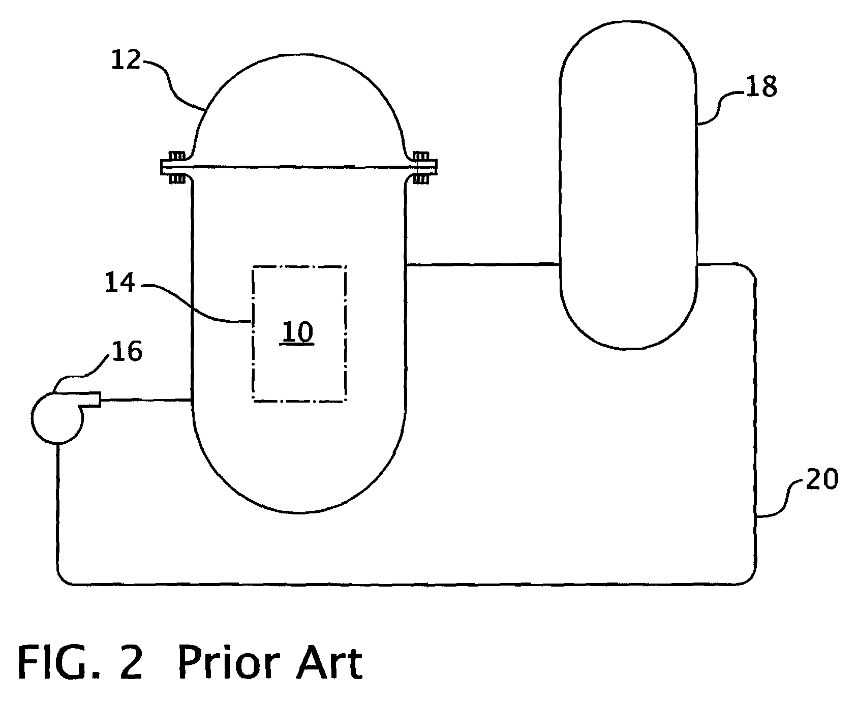
[0024]Referring now to the drawings, FIG. 2 shows a simplified nuclear reactor primary system, including a generally cylindrical reactor pressure vessel 10 having a closure head 12 enclosing a nuclear core 14. A liquid reactor coolant, such as water, is pumped into the vessel 10 by pump 16 through the core 14 where heat energy is absorbed and is discharged to a heat exchanger 18, typically referred to as a steam generator, in which heat is transferred to a utilization circuit (not shown), such as a steam driven turbine generator. The reactor coolant is then returned to the pump 16, completing the primary loop. Typically, a plurality of the above-described loops are connected to a single reactor vessel 10 by reactor coolant piping 20.

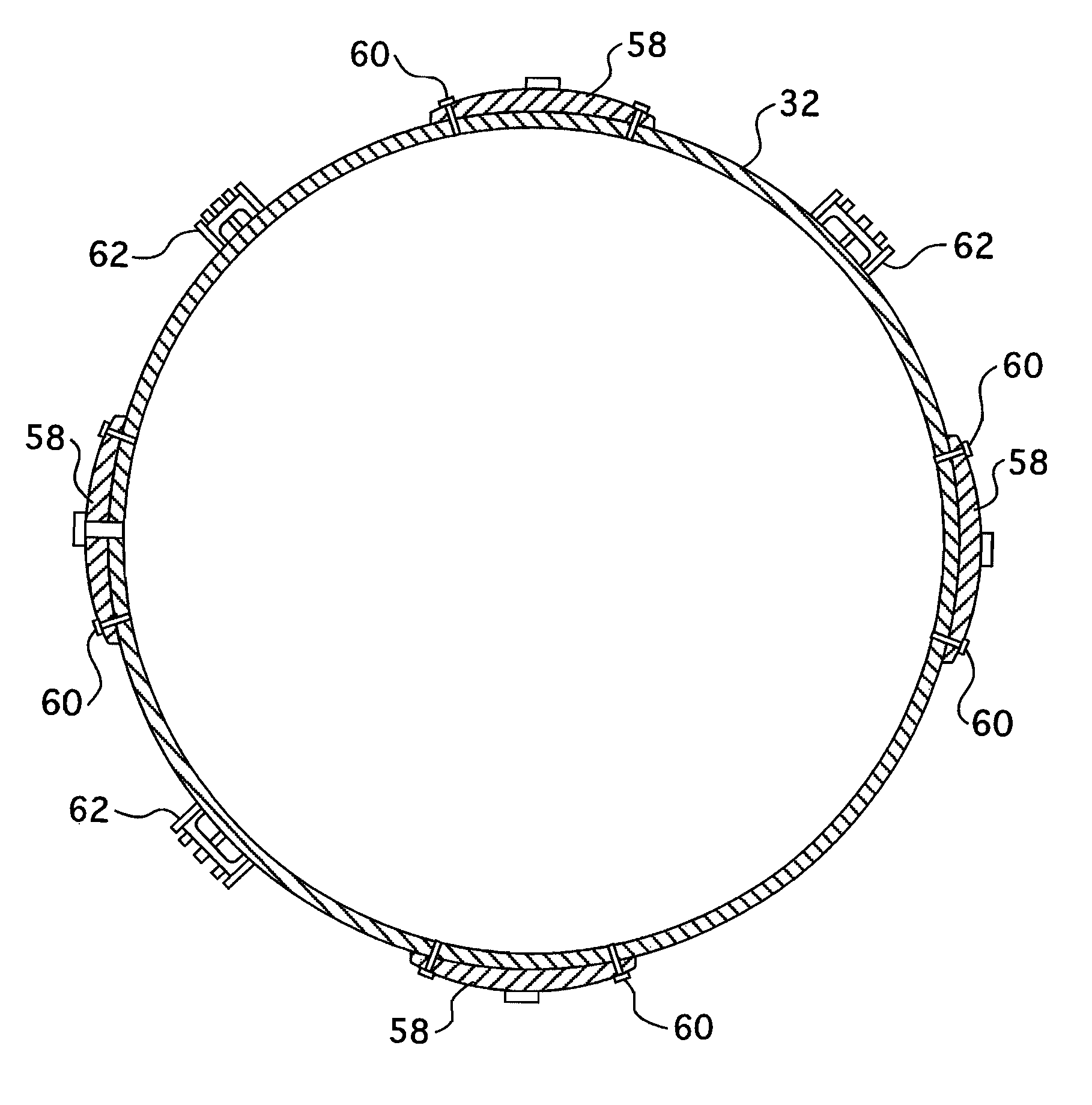
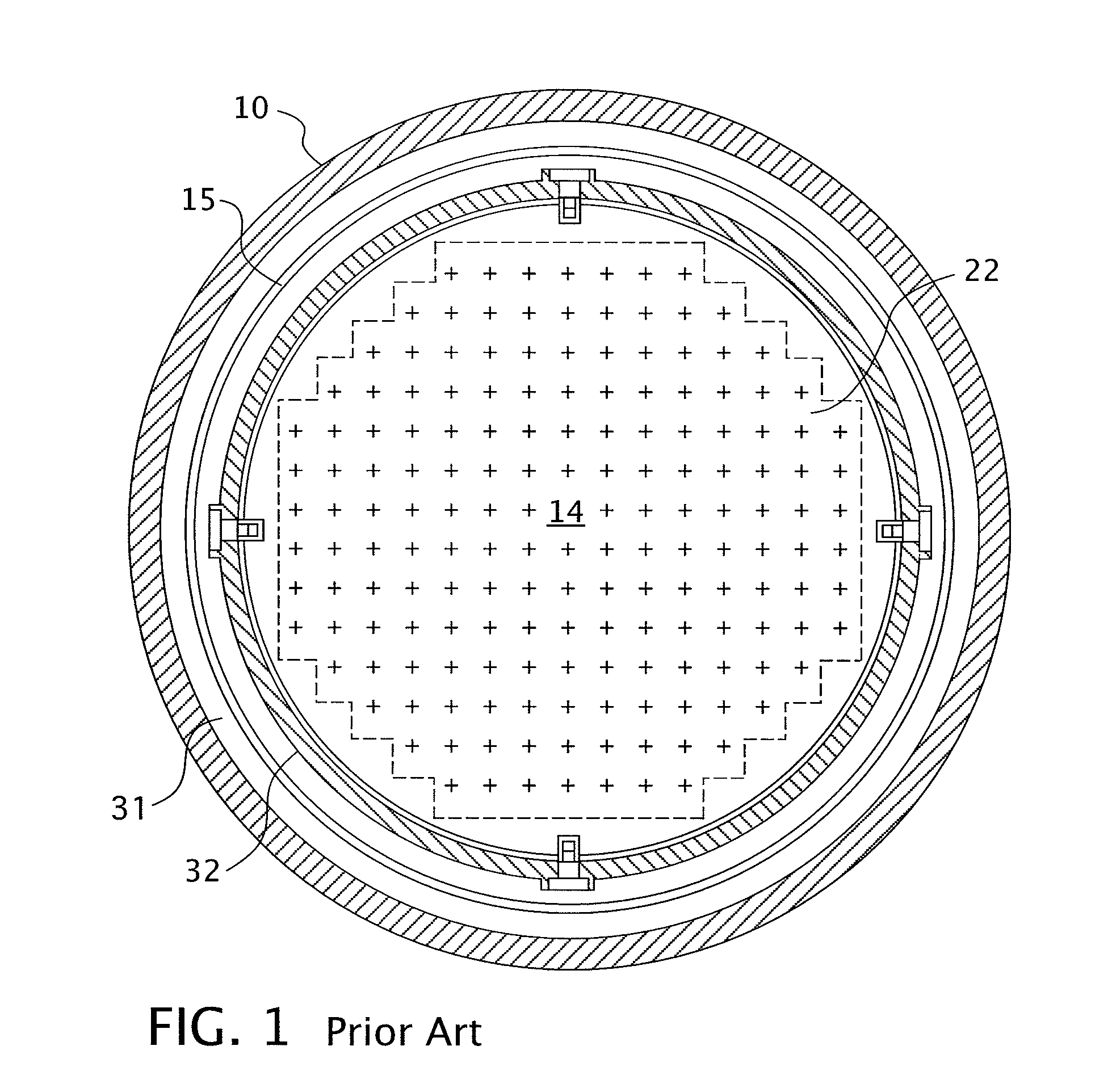
[0025]An exemplary reactor design is shown in more detail in FIG. 3. In addition, to the core 14 comprised of a plurality of parallel, vertically co-extending fuel assemblies 22, for purposes of this description, the other vessel internal structures can ...


PUM


Abstract

In a nuclear reactor neutron panels varying in thickness in the circumferential direction are disposed at spaced circumferential locations around the reactor core so that the greatest radial thickness is at the point of highest fluence with lesser thicknesses at adjacent locations where the fluence level is lower. The neutron panels are disposed between the core barrel and the interior of the reactor vessel to maintain radiation exposure to the vessel within acceptable limits.

Description

CROSS REFERENCE TO RELATED APPLICATIONS[0001]This application claims priority to Provisional Application 60 / 992,158, filed Dec. 4, 2007.GOVERNMENT INTEREST[0002]This invention was made with Government support under Contract No. DE-FC07-051D1436 awarded by the Department of Energy. The Government has certain rights in this invention.BACKGROUND OF THE INVENTION[0003]1. Field of the Invention[0004]The present invention relates generally to nuclear reactor internals and more specifically to neutron shields for shielding nuclear reactor pressure vessels from overexposure to neutron flux.[0005]2. Description of Related Art[0006]The primary side of nuclear reactor power generating systems which are cooled with water under pressure comprises a closed circuit which is isolated from and in heat exchange relationship with a secondary side for the production of useful energy. The primary side comprises the reactor pressure vessel enclosing a core internals structure that supports a plurality of...

Claims


Application Information

Patent Timeline
IPC IPC(8): G21C11/00G21C5/00
CPCG21C11/022G21C11/06Y02E30/40Y02E30/30
Inventor SINGLETON, NORMAN R.
Owner WESTINGHOUSE ELECTRIC CORP
Why Eureka
Try Eureka