Laser range finding system using variable field of illumination flash lidar

a laser range finding and variable field technology, applied in the direction of distance measurement, instruments, surveying and navigation, etc., can solve the problems of quadratic fall-off of illumination with range, distortion or misperception, and location and mapping, and achieve the effect of reducing the number of laser beams

Active Publication Date: 2011-12-06
ROCKWELL COLLINS INC
View PDF20 Cites 181 Cited by
  • Summary
  • Abstract
  • Description
  • Claims
  • Application Information

AI Technical Summary

Benefits of technology

[0013]In a broad aspect, the present invention is a laser range finding system that includes a light detection and ranging (LIDAR) sensor unit (SU) and a LIDAR processor unit (PU). The LIDAR SU is for transmitting light pulses and receiving resulting input light signals reflected from objects within the field of view of the SU. The LIDAR SU includes a flash LIDAR illuminating laser source for transmitting light pulses. The LIDAR illuminating laser source includes an illuminating laser and zoom optics operatively associated with the laser. A LIDAR receiver receives resulting input light signals reflected from the objects. The LIDAR receiver includes a sensor; and, a flash readout integrated circuit (IC). The flash readout IC measures the transit time of the light pulses. The LIDAR processor unit (PU) is operatively associated with the LIDAR SU and it utilizes flash LIDAR ranging. A power source is operatively coupled to the LIDAR PU. Zooming of the transmitted light pulses results in the received resulting input light signals illuminating a relatively reduced area of the frame, thus providing a flash LIDAR image of relatively reduced resolution but enhanced range by utilization of the transit time measurements.

Problems solved by technology

Location and mapping is a fundamental problem in mobile robotics.
Aside from the potential difficulties with rapidly moving parts, the fact that all pixels in a scene are sampled sequentially can lead to distortion or misperception if there is relative motion between the sensor and all or part of the scene.
A major drawback to the use of flash LIDAR is that the spreading of the illuminating laser beam introduces a quadratic fall-off in illumination with range.
In a GPS-Denied Navigation activity for dismounted troops, the range of the flash LIDAR is limited due to the requirement that the LIDAR be body-worn.
None of the aforementioned references provide an efficient flash LIDAR system for laser range finding that is particularly suitable for man worn applications.

Method used


Image

  • Laser range finding system using variable field of illumination flash lidar
  • Laser range finding system using variable field of illumination flash lidar
  • Laser range finding system using variable field of illumination flash lidar

Examples


Embodiment Construction

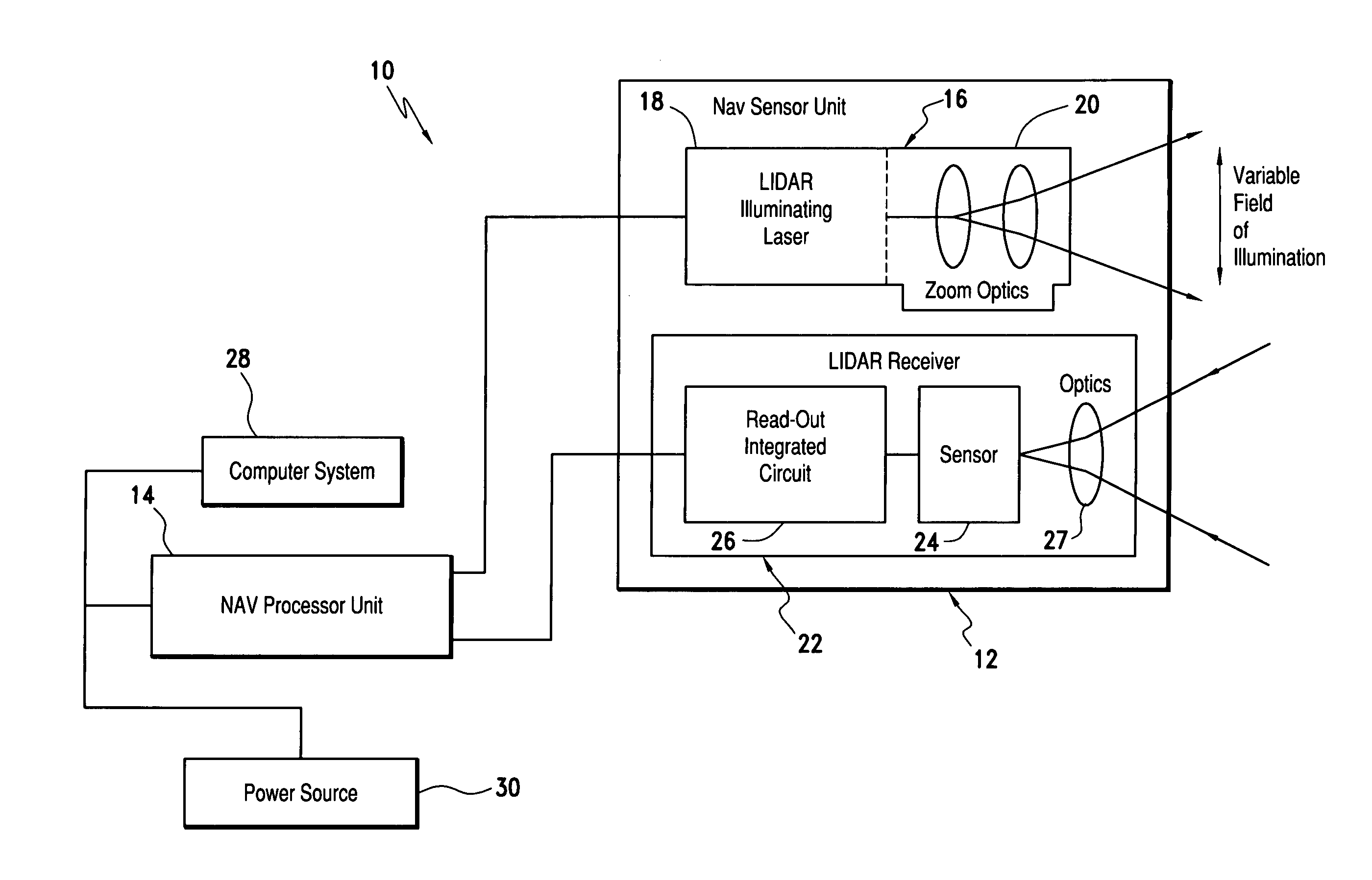
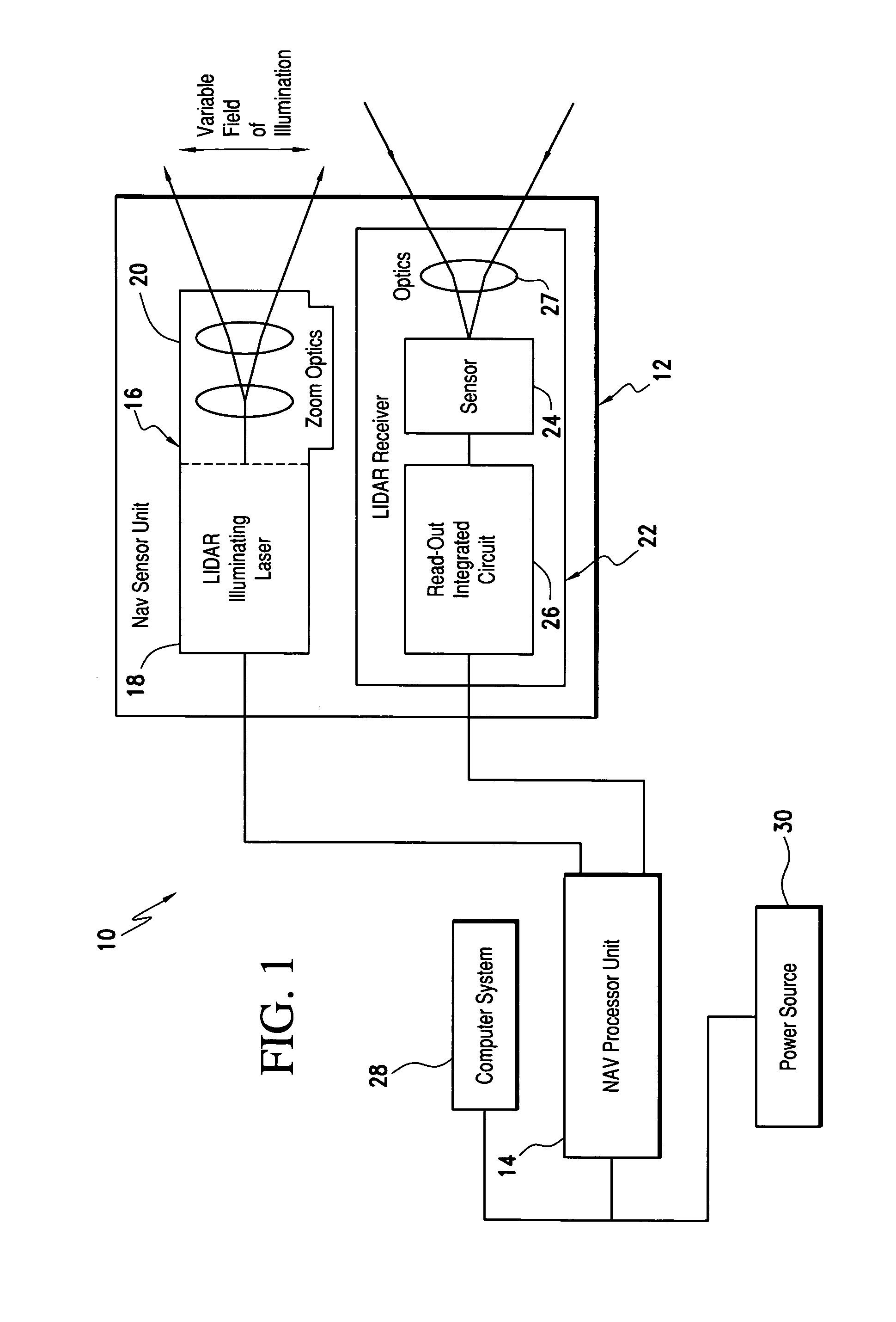
[0021]Referring now to the drawings and the characters of reference marked thereon, FIG. 1 illustrates a laser range finding system, designated generally as 10. A light detection and ranging (LIDAR) sensor unit (SU), designated generally as 12, transmits light pulses and receives resulting input light signals reflected from objects within its field of view. A LIDAR processor unit (PU) 14 is operatively associated with the LIDAR SU 12. The LIDAR PU 14 utilizes flash LIDAR ranging.

[0022]The SU 12 includes a flash LIDAR illuminating laser source 16 for transmitting light pulses. The LIDAR illuminating laser source includes an illuminating laser 18 and zoom optics 20 operatively associated with the laser 18. A LIDAR receiver, designated generally as 22, receives resulting input light signals reflected from the objects within the field of view. The LIDAR receiver includes a sensor 24; and, a flash readout integrated circuit (IC) 26. The flash readout IC 26 measures the transit time of th...


PUM


Abstract

The laser range finding system includes a light detection and ranging (LIDAR) sensor unit (SU) and a LIDAR processor unit (PU). The LIDAR SU is for transmitting light pulses and receiving resulting input light signals reflected from objects within the field of view of the SU. The LIDAR SU includes a flash LIDAR illuminating laser source for transmitting light pulses. The LIDAR illuminating laser source includes an illuminating laser and zoom optics operatively associated with the laser. A LIDAR receiver receives resulting input light signals reflected from the objects. The LIDAR receiver includes a sensor; and, a flash readout integrated circuit (IC). The flash readout IC measures the transit time of the light pulses. The LIDAR processor unit (PU) is operatively associated with the LIDAR SU and it utilizes flash LIDAR ranging. A power source is operatively coupled to the LIDAR PU. Zooming of the transmitted light pulses results in the received resulting input light signals illuminating a relatively reduced area of the frame. Thus, a flash LIDAR image of relatively reduced resolution but enhanced range is provided by utilization of the transit time measurements.

Description

BACKGROUND OF THE INVENTION[0001]1. Field of the Invention[0002]The present invention relates generally to measurement of distance to visual landmarks for applications including navigation and mapping, and more particularly navigation and mapping in a Global Positioning System (GPS) denied environment.[0003]2. Description of the Related Art[0004]There is a growing need to provide underground, urban, and indoor navigation without the use of external augmentation aids or GPS. Tracking or navigation systems often make use of measurements from sensors to aid in determining a location (“localization”) or an orientation (attitude and heading) or a pose (position and orientation) of an object such as a person, a vehicle or a robot as it navigates in an environment, such as within the bounds of a building. A variety of types of sensors are available for such systems, including sensors that measure a relative location between a sensor and a target. An example of such a sensor / target combinat...

Claims


Application Information

Patent Timeline
Patent Type & Authority Patents(United States)
IPC IPC(8): G01C3/08
CPCG01S7/51G01S17/023G01S17/89G01S17/86
Inventor BREIHOLZ, ARLEN E.
Owner ROCKWELL COLLINS INC
Why Eureka
Try Eureka