
Split channel receiver with very low second order intermodulation

a receiver and split channel technology, applied in the field of communications, can solve the problems of reducing the performance of an rf receiver, increasing the size of the die, increasing the cost and complexity, and increasing the power transmitted signal into the receive signal

Inactive Publication Date: 2011-12-06
NORTH STAR INNOVATIONS
View PDF7 Cites 37 Cited by
  • Summary
  • Abstract
  • Description
  • Claims
  • Application Information

AI Technical Summary

Benefits of technology

"The present invention relates to a radio frequency receiver that addresses issues related to multiple modes and networks, noise figure, and second order intermodulation distortion. The invention includes a transconductance amplifier, a pulse generator, a passive double balanced mixer, and a direct coupled complex filter. The invention also includes a method for receiving a radio frequency signal and a calibration method for the RF receiver. The technical effects of the invention include improved performance and reduced complexity and cost."

Problems solved by technology

A higher power transmitted signal may leak into the receive signal in such a system.
Using a SAW filter, LNA, amplifiers, and other components may result in increased die size, current drain, cost, and complexity, and reduced performance of an RF receiver.
As IMD2 increases, the signal-to-noise ratio (SNR) and second order input intercept point (IIP2) may decrease, resulting in degraded performance of the RF receiver.
This interaction may allow a DC offset and imbalance on one channel to amplify the DC offset and imbalance on the other channel, resulting in an increased overall DC offset and imbalance and degraded IIP2.
When the received RF signal is connected to the I and Q mixers from a common node, calibration of the IIP2 levels of the I and Q channels to optimal levels may be difficult.
Because the mismatch and imbalance in each channel may be different, optimizing one channel for optimal IIP2 level may adversely affect the IIP2 level of the other channel, and vice versa, resulting in overall sub-optimal performance.
The combined mismatches and imbalances of the channels may also fall outside of the range of calibration.
IIP2 calibration may therefore be limited when attempting to optimize both I and Q channels in a conventional RF receiver topology.

Method used


Image

  • Split channel receiver with very low second order intermodulation
  • Split channel receiver with very low second order intermodulation
  • Split channel receiver with very low second order intermodulation

Examples


Embodiment Construction

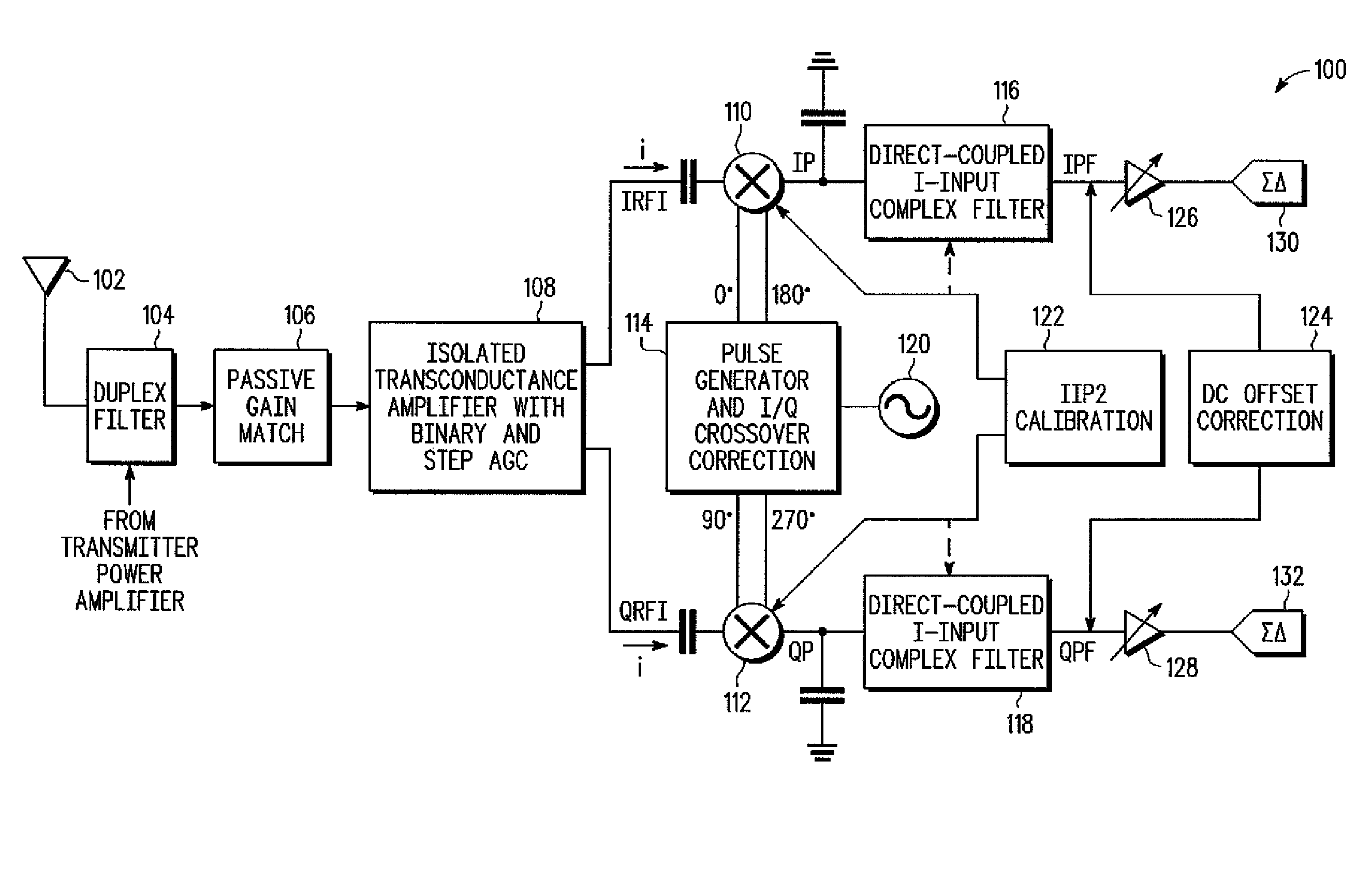
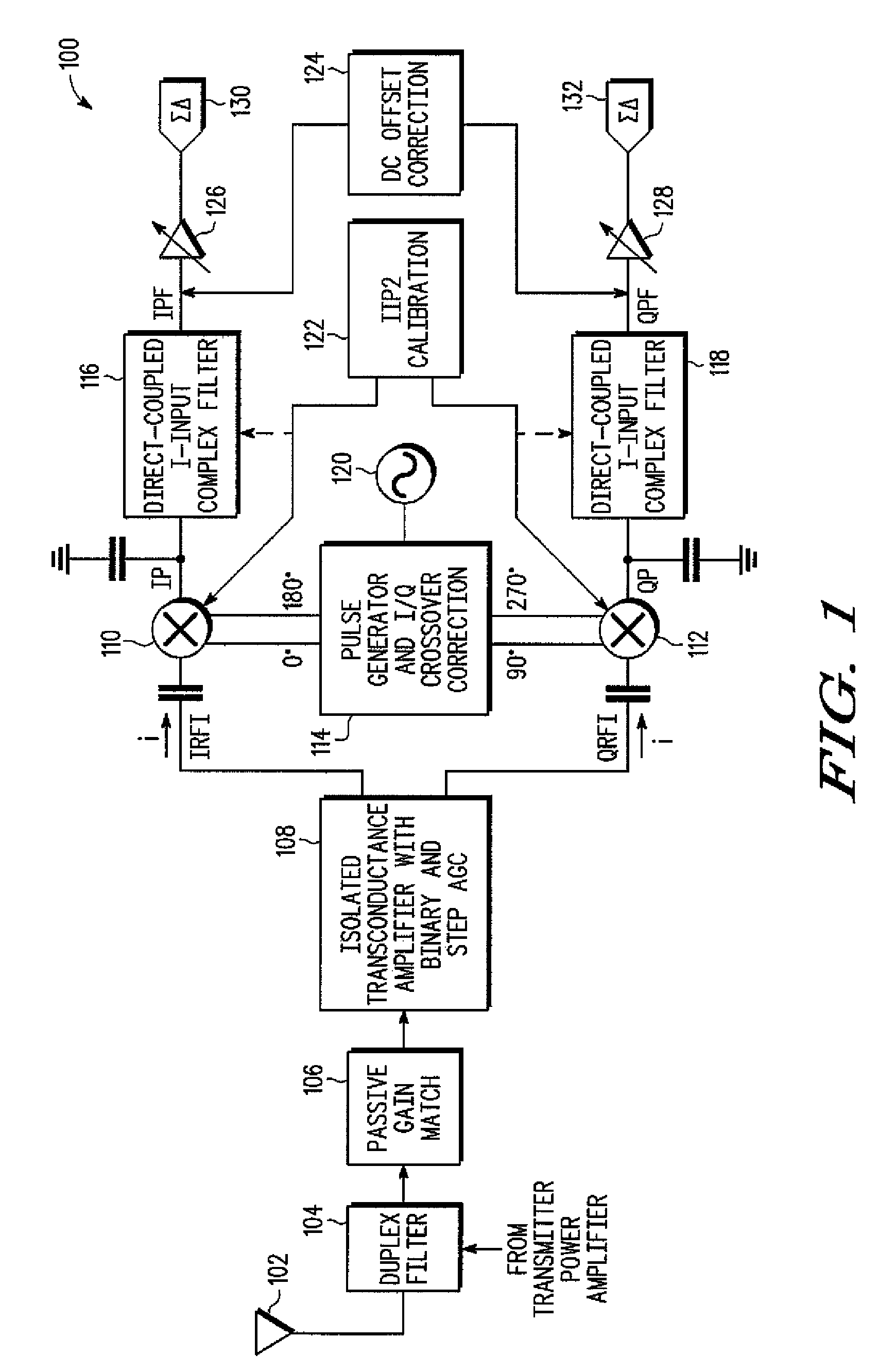
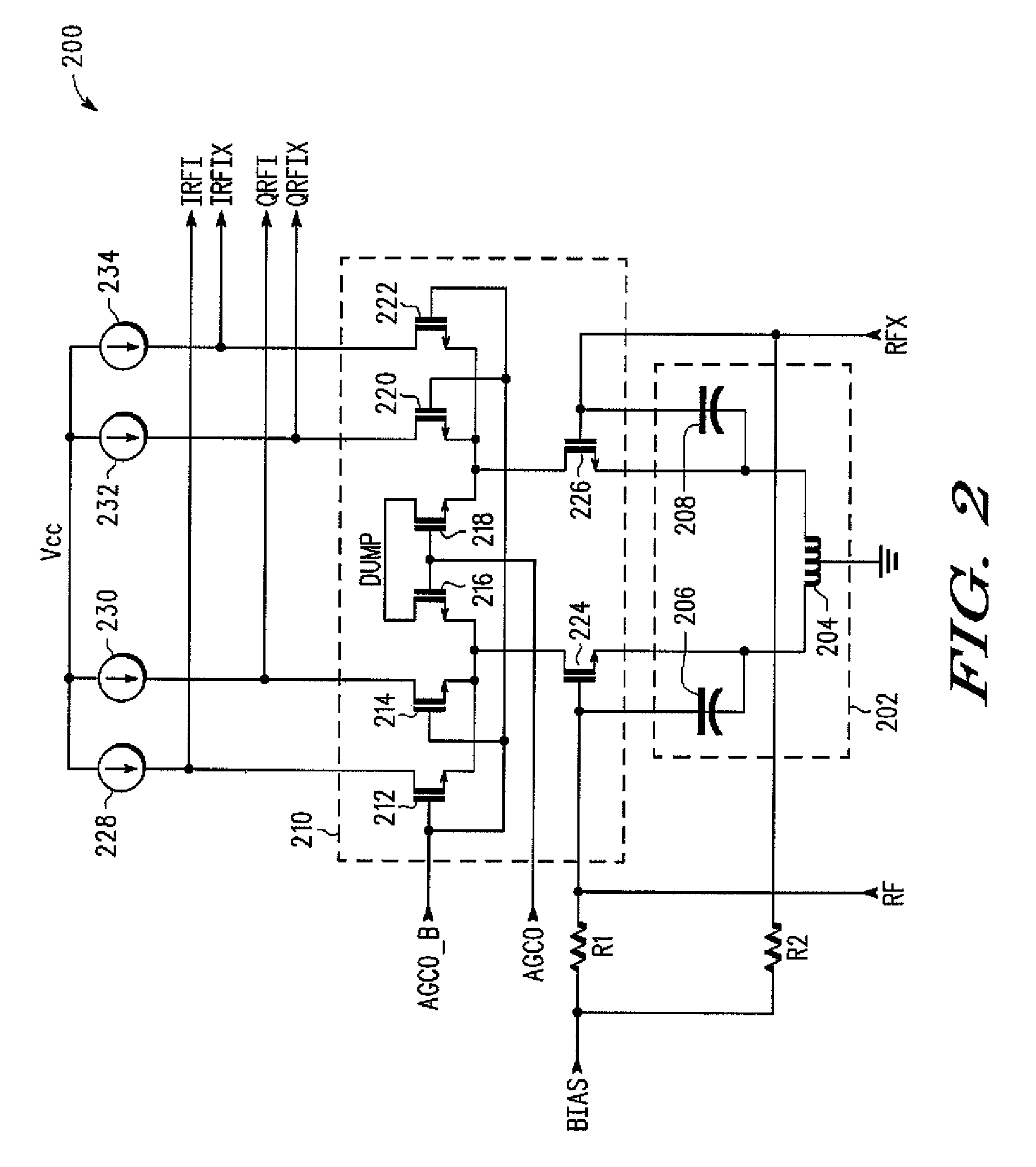
[0017]By way of introduction, the embodiments described below include a radio frequency (RF) receiver including a transconductance amplifier, a pulse generator, a passive double balanced mixer, and a direct coupled complex filter. The transconductance amplifier may amplify and convert a received voltage of an RF signal to electrically isolated in-phase (I) and quadrature (Q) currents. The currents may be injected into the passive double balanced mixer to combine the currents with I and Q pulses to generate I and Q signals. Digital-to-analog converters may generate second order intercept point (IIP2) calibration signals for the I and Q channels. The IIP2 calibration signals may be combined in the mixer with the I and Q pulses when generating the I and Q signals. Adjusting the IIP2 level of the I channel does not affect the IIP2 level of the Q channel, and vice versa. A crossover correction circuit may control an amplitude crossover threshold of the I and Q pulses to reduce the amount...


PUM


Abstract

A high performance radio frequency receiver includes an isolated transconductance amplifier with large binary and stepped gain control range, controlled impedance, and enhanced blocker immunity, for amplifying and converting a radio frequency signal to multiple electrically isolated currents; a pulse generator for generating in-phase and quadrature pulses; a crossover correction circuit and pulse shaper for controlling a crossover threshold of the pulses and interaction between in-phase and quadrature mixers; and a double balanced mixer for combining the RF signal with the pulses to generate an intermediate frequency or baseband zero intermediate frequency current-mode signal. The intermediate frequency signal and second order harmonics may be filtered with a high frequency low pass filter and a current injected complex direct-coupled filter. IIP2 calibration of the in-phase and quadrature channels may be optimized using the isolated transconductance amplifier.

Description

BACKGROUND[0001]1. Field[0002]The present embodiments relate generally to communications, and more specifically, to radio frequency receivers in communications.[0003]2. Related Art[0004]Radio frequency (RF) receivers used in modern communication systems may support multiple modes and networks, such as 3G wideband code division multiple access (WCDMA) and 2G Global System for Mobile communications (GSM), using time division multiple access (TDMA). A received RF signal in a certain mode may be translated into a specified frequency band and processed to retrieve the information contained in the RF signal. For example, an RF receiver may amplify, filter, and mix an analog received RF signal into in-phase (I) and quadrature (Q) signals that may be converted into digital signals for further processing.[0005]The multiple modes may utilize the same RF receiver architecture but have different frequency ranges and linearity, noise figure, and sensitivity requirements. Noise figure is a measur...

Claims


Application Information

Patent Timeline
Patent Type & Authority Patents(United States)
IPC IPC(8): H03K9/00
CPCH04L27/3863H04L27/3872
Inventor KACZMAN, DANIEL L.SHAH, MANISH N.
Owner NORTH STAR INNOVATIONS
Learn More