
Device for layerwise manufacturing of a three-dimensional object

a three-dimensional object and manufacturing technology, applied in the field of three-dimensional object layering manufacturing devices, can solve the problems of less and less transmission of beams, less and less transparency of lenses in the course of manufacturing processes, and reduced work surface intensity

Active Publication Date: 2011-12-13
EOS ELECTRO OPTICAL SYST
View PDF14 Cites 58 Cited by
  • Summary
  • Abstract
  • Description
  • Claims
  • Application Information

AI Technical Summary

Benefits of technology

[0007]In this apparatus a heating element is provided for a coupling window for the electromagnetic radiation in order to raise the temperature of the lens during the building of the three-dimensional object. Due to the increased temperature an accumulation of contaminations on the coupling window is avoided.

Problems solved by technology

In particular, when using plastics as powder material, volatile decomposition and reaction products escape from the powder in the process, which deposit on the lens and thus more and more reduce the transparency of the lens in the course of the manufacturing process.
This leads to the situation that the laser beam is less and less transmitted, whereby its intensity in the work surface decreases.
Due to the decreasing intensity the quality of the object to be manufactured degrades.
However, as the nitrogen only partially overflows over the safety glass and as no flow is present between the nozzles, at these positions the contaminations deposit.

Method used


Image

  • Device for layerwise manufacturing of a three-dimensional object
  • Device for layerwise manufacturing of a three-dimensional object
  • Device for layerwise manufacturing of a three-dimensional object

Examples


first embodiment

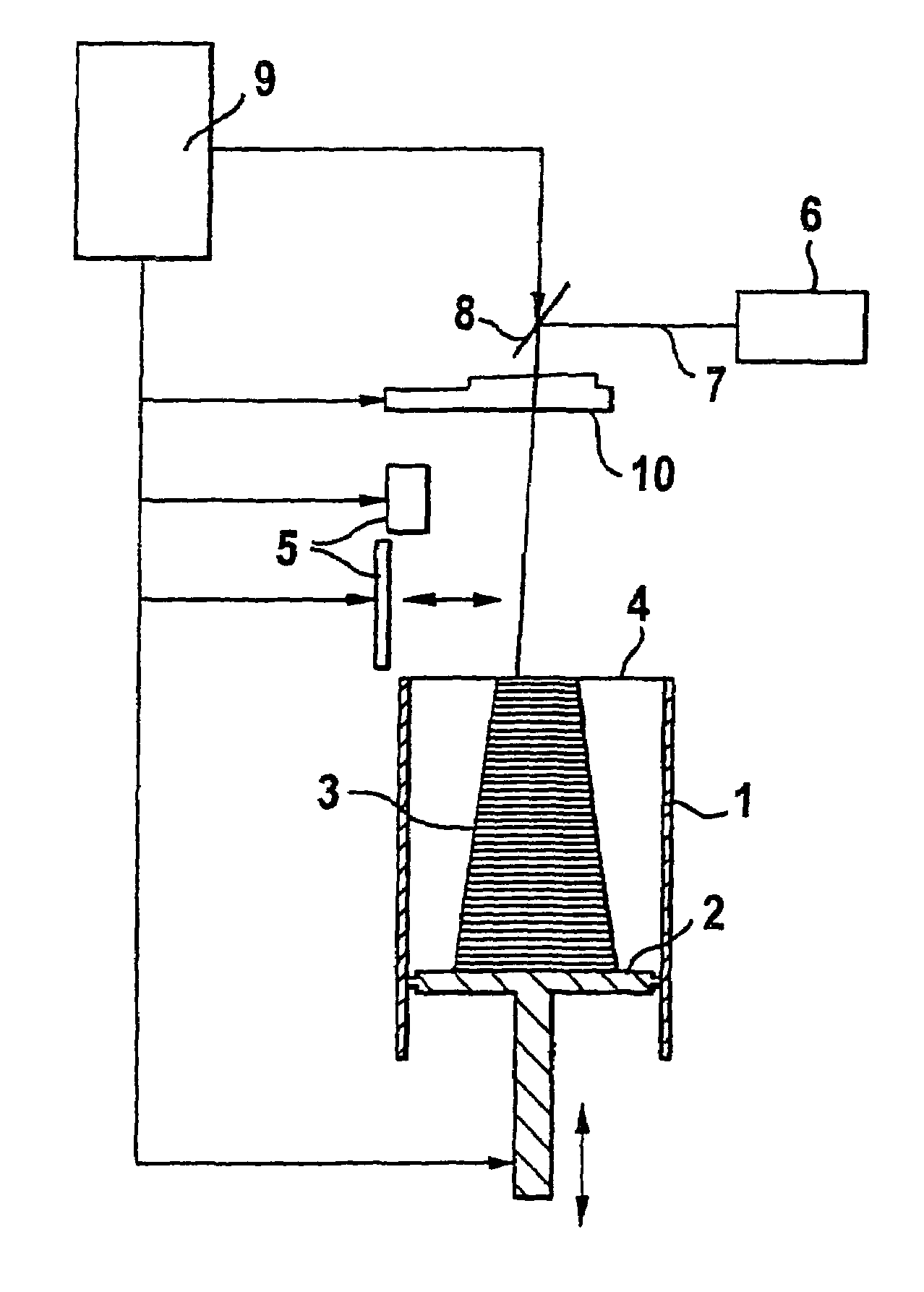
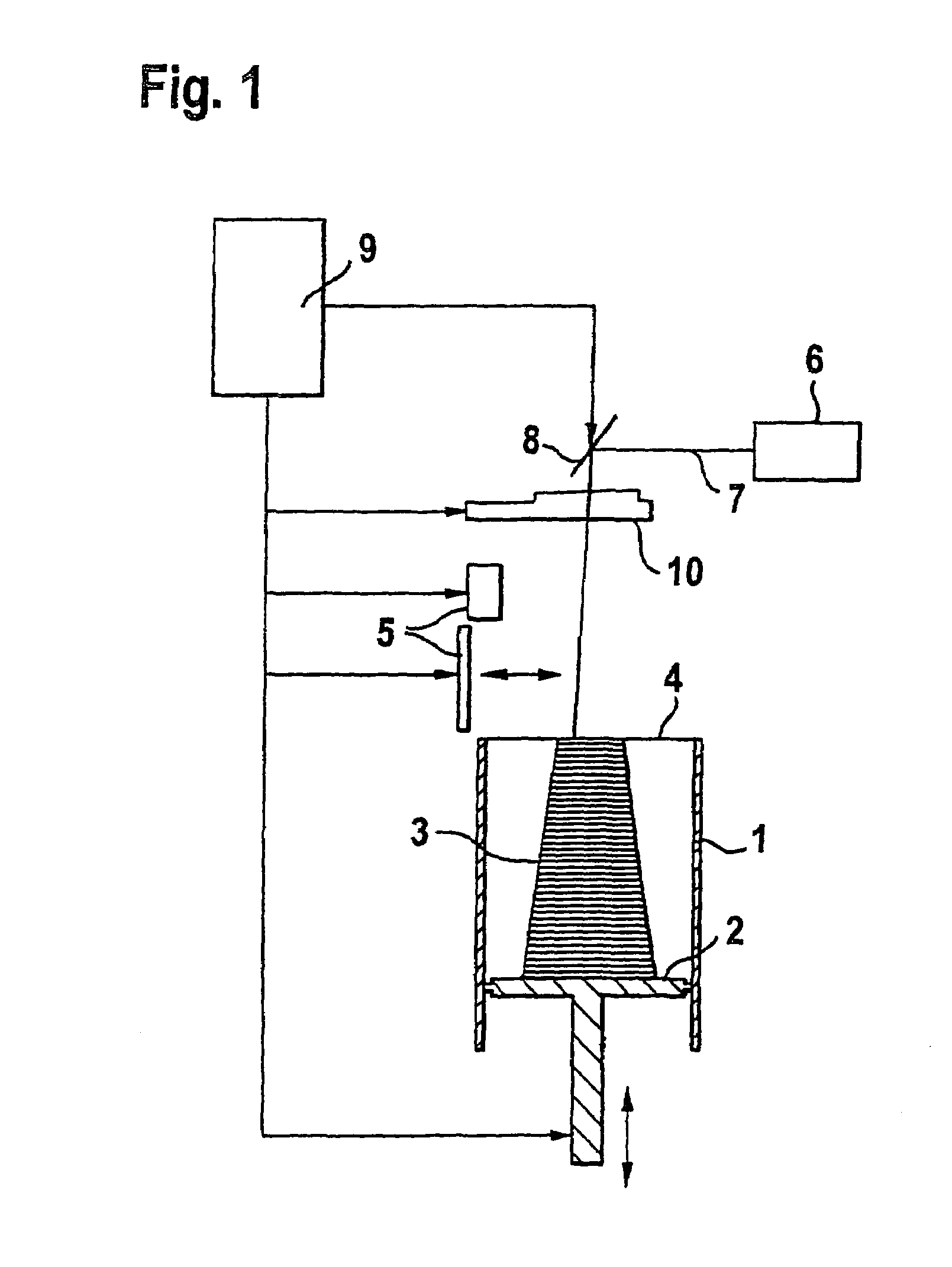
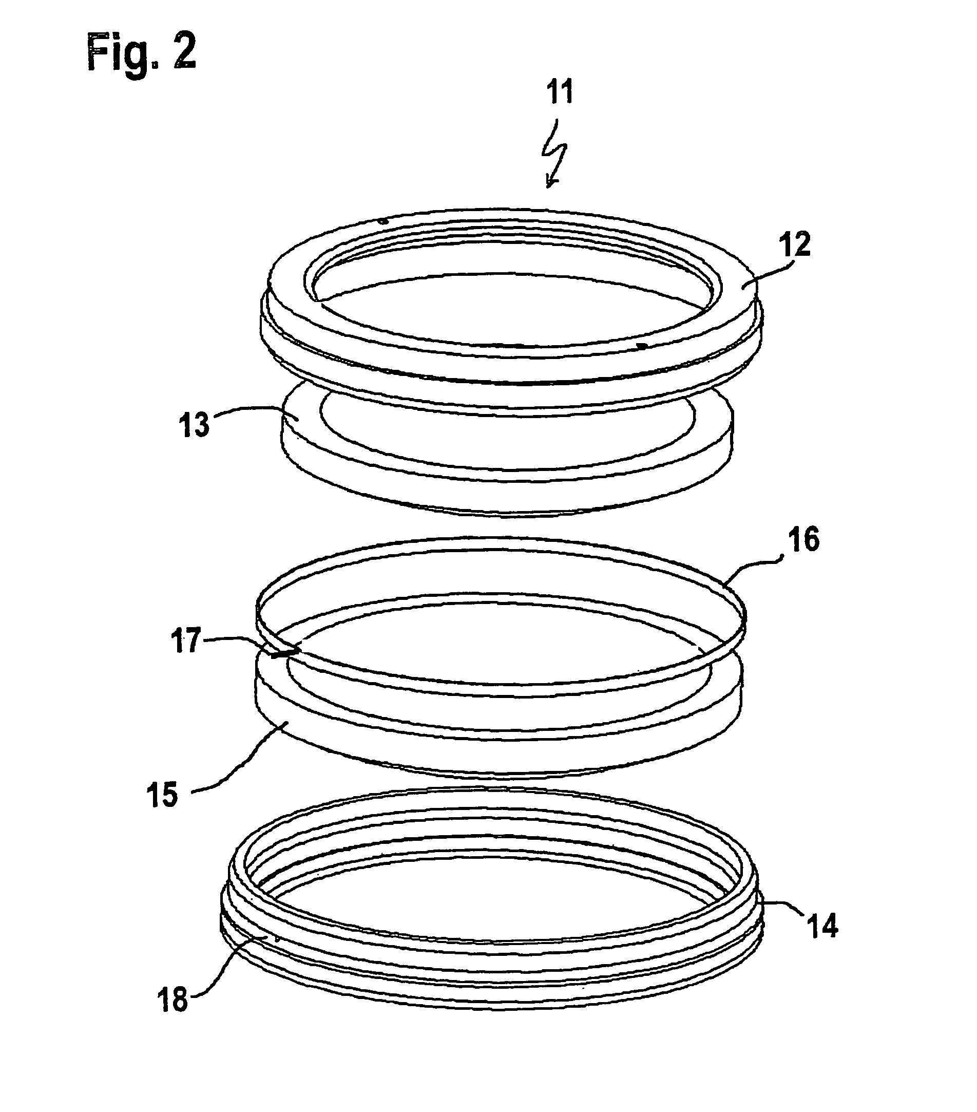
[0016]Referring to FIG. 1 to 4 in the following an apparatus for layerwise manufacturing of a three-dimensional object according to the present invention is described.

[0017]As can be seen in FIG. 1, the apparatus for layerwise manufacturing of an object comprises a container 1 that is open at the top. A support 2, which is movable in a vertical direction and supports the object 3 to be formed, is placed in this container 1. The support 2 is positioned in the vertical direction such that the layer of the object 3 to be solidified in each case lies within a working plane 4. Further, an application device 5 for applying the building material in powder form that can be solidified by electromagnetic radiation is provided. The apparatus comprises a laser 6. The laser beam 7, which is generated by the laser 6, is deflected by a deflecting device 8 that is controlled by a control device 9 and is focussed at a predetermined point within the working plane 4 by a focussing device 10.

[0018]The ...

second embodiment

[0027] the heating element 16 is formed from a layer 21 of an electrically conducting material as for example metal, graphite etc., which is formed by vapor deposition or printing on the edge of the exit lens 15, which does not serve for focussing the laser beam 7. Alternatively, also a metal or graphite foil or a carrier foil being coated with a conducting material can be glued onto the edge of the lens.

[0028]For increasing the electrical resistance the conducting layer 21 may be structured, for example such that it is formed in the shape of a meander.

[0029]This embodiment may be advantageously also applied to lenses having a non-circular rim.

[0030]In the above described embodiments connections of the electrical leads 17 to the heating element 16 may for example be accomplished by leading through the cables directly, by crimping or soldering onto cables having a higher mechanical strength in the inner of the lens mount, by contact clamping in the container, etc.

[0031]In all embodim...


PUM

PropertyMeasurementUnit
temperatureaaaaaaaaaa
electromagneticaaaaaaaaaa
electrically conductingaaaaaaaaaa

Abstract

An apparatus for layerwise manufacturing of a three-dimensional object by solidification of a material, which can be solidified via electromagnetic radiation, includes a source for the electromagnetic radiation, a building space for manufacturing the three-dimensional object, a coupling window, for transmitting the electromagnetic radiation into the building space and a heating element for heating the coupling window. By the heating element the temperature of the lens is increased during the building of the three-dimensional object. By the increased temperature the accumulation of contamination on the coupling window is prevented.

Description

BACKGROUND OF THE INVENTION[0001]The present invention is related to a device for layerwise manufacturing of a three-dimensional object.[0002]Such devices are known in the prior art for example as devices for stereolithography, laser sintering etc.[0003]Thus, for example a device for layerwise manufacturing of an object by laser sintering is known to the applicant, which has a support for positioning of the object relative to a work surface and a device for applying a powder that can be solidified by electromagnetic radiation. The apparatus comprises a laser. The laser beam that has been generated by the laser is focussed via lenses onto a spot within the work surface by a focussing device and solidifies the powder. In particular, when using plastics as powder material, volatile decomposition and reaction products escape from the powder in the process, which deposit on the lens and thus more and more reduce the transparency of the lens in the course of the manufacturing process. Thi...

Claims


Application Information

Patent Timeline
Patent Type & Authority Patents(United States)
IPC IPC(8): B28B7/04
CPCB23K26/16B29C67/0066B29C67/0077G02B7/025G02B7/028G02B27/0006B29C64/135B29C64/153B33Y30/00B33Y10/00B33Y40/00Y02P10/25
Inventor FRUTH, ALBERTPERRET, HANS
Owner EOS ELECTRO OPTICAL SYST
Learn More