Apparatus comprising an ion mobility spectrometer

a technology of ion mobility and apparatus, which is applied in the direction of mass spectrometers, instruments, separation processes, etc., can solve problems such as undesired effects and particularly problematic effects, and achieve the effects of low centre-of-mass collision energies, high ionic mobility, and low strength

Active Publication Date: 2011-12-13
MICROMASS UK LTD
View PDF19 Cites 4 Cited by
  • Summary
  • Abstract
  • Description
  • Claims
  • Application Information

AI Technical Summary

Benefits of technology

[0118]According to the preferred embodiment helium gas is preferably provided in or to the first chamber. Helium gas is particularly advantageous since it results in low centre-of-mass collision energies with ions and hence ions entering the first chamber will preferably not be substantially fragmented. Furthermore, ions possess a relatively high ionic mobility as they pass through helium gas and hence ions will preferably not suffer from ion mobility discrimination effects. Therefore, according to an embodiment a relatively low strength electric field may be used to drive or inject ions into the chamber housing the ion mobility spectrometer and the possibility of undesired ion fragmentation and undesired ion mobility discrimination effects prior to ions entering the chamber housing the ion mobility spectrometer can be considerably reduced.
[0119]According to the preferred embodiment the ion mobility spectrometer or separator is preferably provided at sub-atmospheric pressure. The ion mobility spectrometer or separator preferably exhibits good separation characteristics without use of excessively high gas pressures. The ion mobility spectrometer or separator preferably comprises a chamber which is divided into two sub-chambers which are preferably maintained at substantially the same pressure and which are preferably separated by an aperture. The first sub-chamber preferably predominantly contains a relatively light gas, such as helium, and preferably minimises ion fragmentation and / or discrimination effects as ions enter the first sub-chamber from a relatively low pressure chamber or region. The second sub-chamber preferably predominantly contains a relatively heavy gas, such as argon or nitrogen, and preferably provides good ion mobility separation characteristics for the ions.

Problems solved by technology

The requirement to drive ions into the chamber housing the ion mobility spectrometer against a significant outflow of gas can be particularly problematic especially if some of the ions are relatively fragile or have relatively low mobilities since the use of a relatively high electric field to drive the ions into the relatively high pressure chamber can lead to undesired effects such as ion fragmentation and / or ion mobility effects.

Method used


Image

  • Apparatus comprising an ion mobility spectrometer
  • Apparatus comprising an ion mobility spectrometer
  • Apparatus comprising an ion mobility spectrometer

Examples


Embodiment Construction

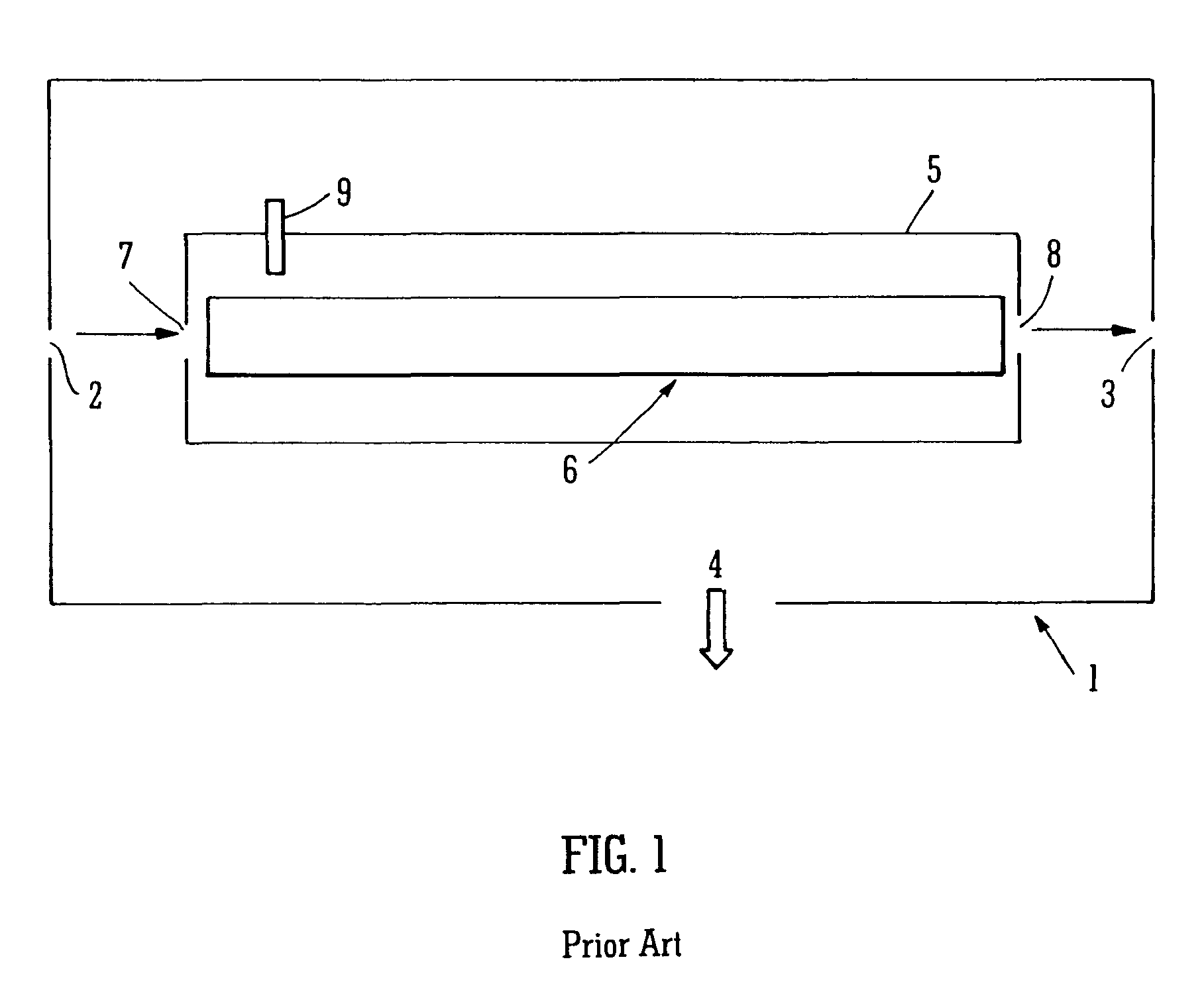
[0123]A section or portion of a conventional ion mobility spectrometer is shown in FIG. 1. A differential pumping chamber 1 is shown having an entrance differential pumping aperture 2 and an exit differential pumping aperture 3. An ion mobility spectrometer or separator 6 is provided within an IMS chamber 5. The IMS chamber 5 has an entrance 7 and an exit 8 and is located within the differential pumping chamber 1. Additional vacuum chambers (not shown) are located upstream and downstream of the differential pumping chamber 1 shown in FIG. 1.

[0124]The ion mobility spectrometer 6 is filled or supplied with gas via a gas outlet 9. The gas exits the IMS chamber 5 via both the entrance aperture 7 and the exit aperture 8 into the differential vacuum chamber 1 which surrounds the IMS chamber 5. The differential vacuum chamber 1 is pumped by a vacuum pump (not shown) which is connected to the differential vacuum chamber 1 via a port 4 in order to maintain the differential vacuum chamber 1 a...


PUM


Abstract

A mass spectrometer is disclosed comprising a first chamber (10) and a second chamber (5). The second chamber (5) is located downstream of the first chamber 10 and an inter-chamber aperture (12) is provided between the two chambers (5,10). An ion guide (13) is located in the first chamber (10) and an ion mobility spectrometer (6) is located in the second chamber (5). Helium gas is provided to the first chamber (10). As ions are accelerated towards the ion mobility spectrometer 6 from a relatively low pressure region they pass initially into the first chamber (10). The helium gas provided in the first chamber (10) minimises ion fragmentation and ion discrimination effects as ions are accelerated into a relatively high pressure region. The ions are then transmitted by the ion guide (13) and are subsequently transmitted to the ion mobility spectrometer (6) located in the second chamber (5).

Description

CROSS REFERENCE TO RELATED APPLICATIONS[0001]This application is the National Stage of International Application No. PCT / GB2007 / 002622, filed Jul. 12, 2007 and designating the United States, which claims benefit of and priority to U.S. Provisional Patent Application No. 60 / 827,892, filed Oct. 3, 2006, United Kingdom Patent Application No. 0613900.0, filed Jul. 13, 2006, and United Kingdom Patent Application No. 0618110.1, filed Sep. 14, 2006. The entire contents of these applications are incorporated herein by reference.BACKGROUND OF THE INVENTION[0002]The present invention relates to apparatus comprising an ion mobility spectrometer, a mass spectrometer, a method of ion mobility spectrometry and a method of mass spectrometry.[0003]Ion mobility spectrometers (“IMS”) are known which are provided at sub-ambient pressure conditions within the vacuum chamber of a mass spectrometer. Typically, the chamber housing the ion mobility spectrometer is maintained at a gas pressure in the range ...

Claims


Application Information

Patent Timeline
Patent Type & Authority Patents(United States)
IPC IPC(8): B01D59/44H01J49/40
CPCG01N27/622H01J49/0481H01J49/062H01J49/004G01N27/623
Inventor GILES, KEVIN
Owner MICROMASS UK LTD
Why Eureka
Try Eureka