Coil component, transformer and switching power supply unit

a technology of transformer and coil, applied in the direction of inductance, inductance with magnetic core, basic electric elements, etc., can solve the problems of deterioration in the function of devices disposed, large amount of heat generated by the coil, and degradation of the coil itself, so as to enhance the dissipation of heat generated in the coil winding, and improve the effect of heat dissipation

Inactive Publication Date: 2011-12-13
TDK CORPARATION
View PDF16 Cites 2 Cited by
  • Summary
  • Abstract
  • Description
  • Claims
  • Application Information

AI Technical Summary

Benefits of technology

[0006]In view of the problems described above, an object of the present invention is to provide a coil component, a transformer, and a switching power supply unit of enhanced heat dissipation of the heat generated in coil windings.
[0008]With the coil component, since the connecting member for electrically connecting the ends of the first coil winding and the second coil winding together is further coupled with the heat conductive member having electrical insulation properties, the heat generated in the first and second coil windings can be dissipated through the heat conductive member, which further enhances heat dissipation of the heat generated in the first and second coil windings.
[0011]In this case, as the members of the same form can be used for the first and second coil windings, the steps to manufacture each of the coil windings individually can be omitted, thereby reducing the amount of work to manufacture the coil windings.
[0012]The first coil winding and the second coil winding each may be composed by joining a plurality of plate-like coil members in a ring shape having ends. Accordingly, when each of the first coil winding and the second coil winding is formed by joining the plate-like coil members together, the current flowing through these coil windings becomes extremely large. By installing the heat conductive member so as to dissipate heat, the deterioration in function of the coil component or the like can be avoided more adequately.
[0017]As described above, since the heat conductive member is in contact with the chassis of the switching power supply unit, the connecting member is coupled with the chassis with the heat conductive member interposed therebetween. For example, when the chassis of the switching power supply unit serves as a part of a heat sink, the heat generated in the coil windings can be dissipated more effectively through the heat conductive member to the chassis, which further enhances the dissipation of the heat generated in the coil windings.
[0018]According to the present invention, a coil component, a transformer, and a switching power supply unit of enhanced heat dissipation of the heat generated in coil windings can be provided.

Problems solved by technology

However, when the coil component disclosed in JP-U-H2-004217 is applied to, for example, a choke coil in a switching power supply unit, a large amount of current flows through a coil constituting the coil component, whereby a large amount of heat is generated from the coil.
The heat generated may cause degradation of the coil itself or deterioration in function of devices disposed in periphery of the coil component, for example.

Method used


Image

  • Coil component, transformer and switching power supply unit
  • Coil component, transformer and switching power supply unit
  • Coil component, transformer and switching power supply unit

Examples


Embodiment Construction

[0030]Embodiments of the present invention will now be described in details with reference to accompanying drawings, wherein like numbers reference like elements and their redundant descriptions are omitted.

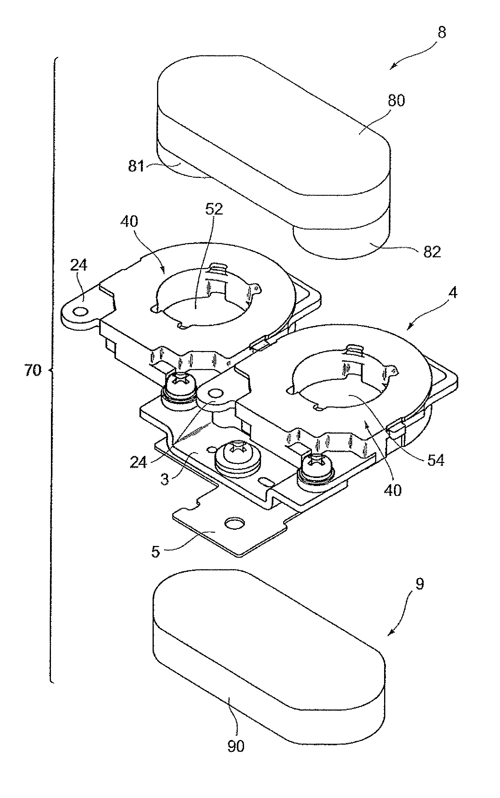
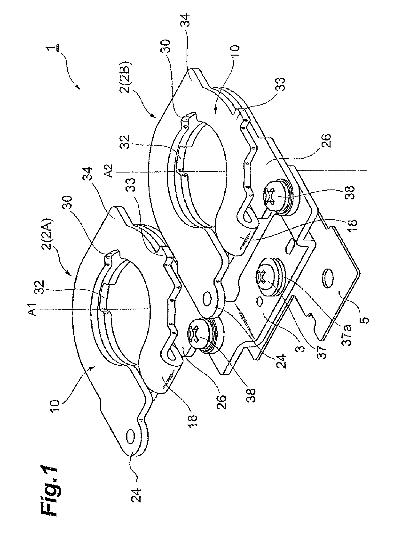
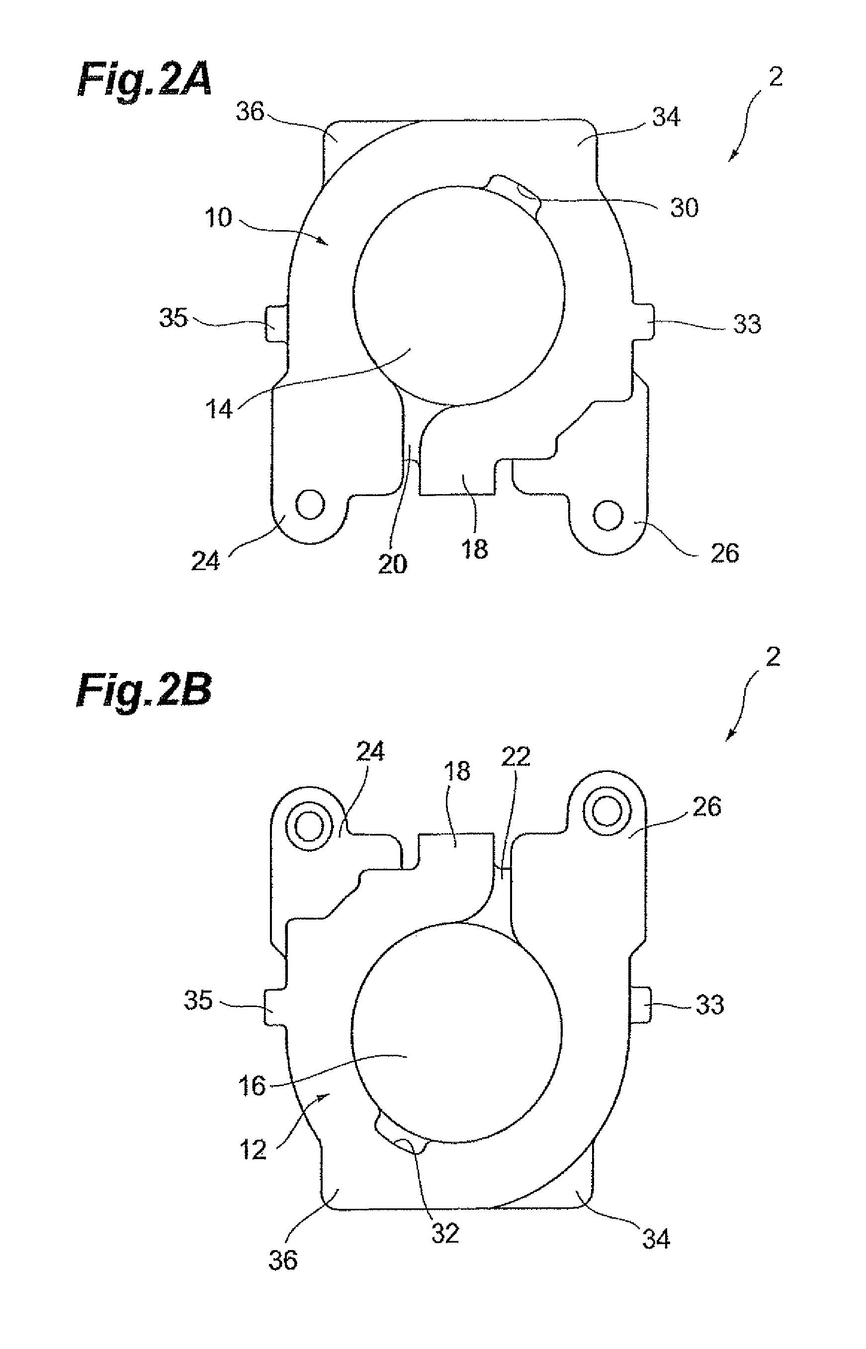
[0031]With reference to FIGS. 1 to 3, the structure of a coil component according to an embodiment of the present invention will be described first. FIG. 1 is a perspective view of the coil component according to the present embodiment. FIG. 2A is a plan view of a coil winding constituting the coil component, and FIG. 2B is a bottom view of the coil winding. FIG. 3 is a side view of the coil winding.

[0032]A coil component 1 shown in FIG. 1 is the one used for an inductance element, a switching power supply unit such as a converter and an inverter, a noise filter, and the like. The coil component 1 is structured to include two pieces of coil windings 2 (first coil winding 2A and second coil winding 2B) composed of conductive plates, a connecting member (connecting bus bar) 3 for e...


PUM

PropertyMeasurementUnit
currentaaaaaaaaaa
voltageaaaaaaaaaa
voltageaaaaaaaaaa

Abstract

A coil component includes a first coil winding wound around a first axis, a second coil winding wound around a second axis and juxtaposed to the first coil winding, a connecting member for electrically connecting second terminals that are one end of the first coil winding and one end of the second coil winding, and a heat conductive member mounted on the connecting member and having electrical insulation properties and heat conductivity. The first and second coil windings are each wound such that magnetic flux is generated by a current flowing through the first and second coil windings to pass through an opening of the first coil winding and through an opening of the second coil winding in an opposite direction to the direction passing the opening of the first coil winding. Accordingly, heat generated in the first and second coil windings is dissipated from the heat conductive member.

Description

BACKGROUND OF THE INVENTION[0001]1. Field of the Invention[0002]The present invention relates to a coil component, a transformer, and a switching power supply unit.[0003]2. Related Background Art[0004]As a component installed in an automobile, there is known a switching power supply unit such as a DC-DC converter for converting a high voltage to a low voltage or converting a low voltage to a high voltage. As one of the coil components used for a switching power supply unit, there is one known as disclosed in Japanese Utility Model Publication No. JP-U-H2-004217. The coil component disclosed in JP-U-H2-004217 is structured to have two pieces of magnetic core legs (leg portions) and two pieces of magnetic core bases with windings wound around each of the leg portions such that magnetic flux that passes through both of the leg portions and the bases in one direction in a loop is formed.SUMMARY OF THE INVENTION[0005]However, when the coil component disclosed in JP-U-H2-004217 is applied...

Claims


Application Information

Patent Timeline
Patent Type & Authority Patents(United States)
IPC IPC(8): H01F27/28H01F27/08
CPCH01F27/22H01F27/2852H01F27/2876H01F27/303H01F2027/2861H01F27/2895
Inventor IKEZAWA, AKIRA
Owner TDK CORPARATION
Why Eureka
Try Eureka