Deployable antenna system

a technology of antenna system and deployment, which is applied in the direction of satellite radio beaconing, measurement devices, instruments, etc., can solve the problems of not being suitable for a rapid deployment system and causing difficulties

Active Publication Date: 2011-12-13
BAE SYSTEMS PLC
View PDF16 Cites 10 Cited by
  • Summary
  • Abstract
  • Description
  • Claims
  • Application Information

AI Technical Summary

Benefits of technology

[0012]In accordance with the invention, it is preferred to employ an active antenna to shorten the overall length of the antenna and to enable broadband reception (8-20 MHz). Active antennae are known, and employ an active electrical circuit which functions as an impedance buffer between the antenna and receiver, and enables an optimal matching of the antenna to the receiver input.
[0014]However as particularly preferred and in accordance with the invention, it is preferred to employ on the grounds of expense and accuracy, for each antenna element, a receiver of a satellite radio navigation system, commonly known as GNSS (Global Navigation Satellite Systems), including GPS, GLONASS and Galileo. This may provide the required degree of accuracy of location, and does not require expensive equipment for radio location to be installed at a central station of the antenna system.
[0015]Such receiver of a satellite radio navigation system may also be used for synchronisation purposes. In particular GPS provides a standard timing signal provided by an atomic clock, comprising pulses spaced 1 sec apart, with 100 nsec accuracy. This timing signal may be employed both to synchronise a clock and a local oscillator in each receiver of each antenna element. This avoids the need for having a master timing source and a master frequency source.

Problems solved by technology

By placing receivers at the base of the elements, difficulties arise in that the elements have to be synchronised in time, frequency and phase in order that the radar system function accurately.
Further their position relative to one another needs to be known accurately, but since they are positioned by hand by technicians without scientific instruments to permit accurate placement, (desirably to within 0.1 meters) this is a further problem.
Whilst a wide variety of HF antenna arrays are known comprising a multiplicity of antenna elements, such elements are normally fixedly mounted together in a framework or other mounting arrangement—this would not be suitable for a rapidly deployable system, in particular where the elements are spaced a long distance apart.

Method used


Image

  • Deployable antenna system
  • Deployable antenna system
  • Deployable antenna system

Examples


Embodiment Construction

[0022]Embodiments of the present invention will now be described in more detail, and by way of example only, with reference to the accompanying drawings.

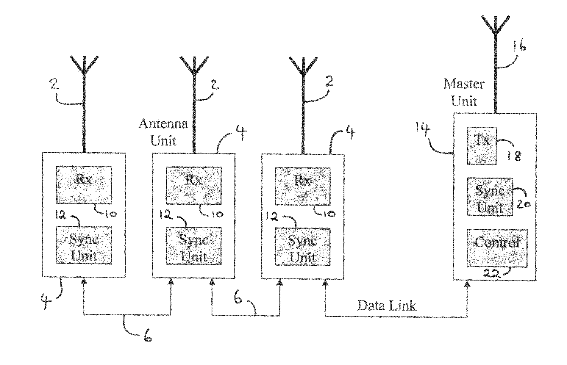
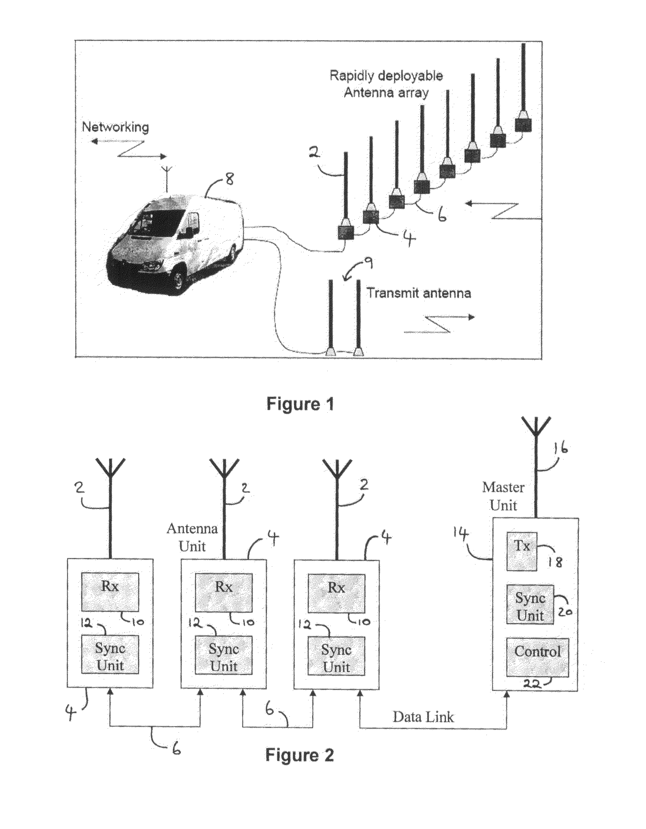
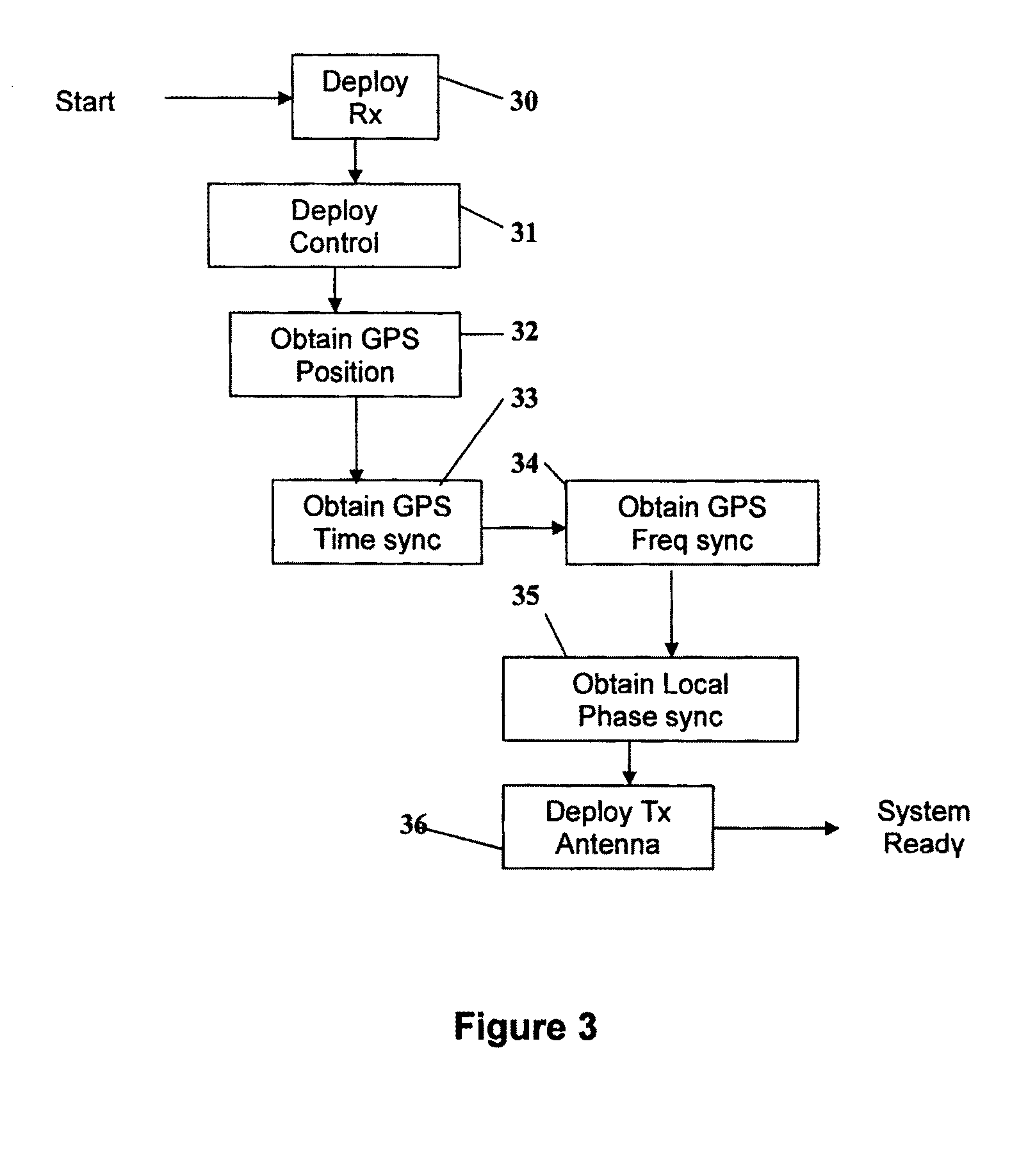
[0023]The preferred embodiment of the invention relates to a distribution, reference, synchronisation and calibration scheme for a phased array receiving system of an HF radar system. It simplifies installation of the phased array and enables rapid deployment and automatic synchronisation and calibration of the array. It has particular application to HF radar where phased array antennas are physically large, but also has application to general phased array implementations.

[0024]The design of a phased array antenna involves a decision on how the elements will be deployed, how the signals to or from the elements will be distributed, how the signals will be synchronised and how the array will be aligned or calibrated. Additionally an attractive proposition is to integrate the receiver or transmitter with each antenna element, which fur...


PUM


Abstract

A rapidly deployable HF surface wave radar phased array antenna system is provided, including a plurality of separate antenna elements that are relatively movable to desired spaced apart positions, each antenna element including a respective receiver for receiving HF radio signals, wherein, in order to determine and control properties of the radar system, each element includes a GPS receiver for determining the location of each element and for timing and frequency synchronization.

Description

RELATED APPLICATION INFORMATION[0001]This application is a United States National Phase patent application of, and claims the benefit of, International Patent Application No. PCT / GB2007 / 050397 which was filed on Jul. 12, 2007, and which claims priority to British Patent Application No. 0614093.3, which was filed on Jul. 14, 2006 and European Patent Application No. 06253698.2, which was filed on Jul. 14, 2006, the disclosures of each of which are incorporated herein by reference.FIELD OF THE INVENTION[0002]The present invention relates to a deployable antenna system, particularly though not exclusively, an HF radar phased array antenna system that is adapted for rapid deployment.BACKGROUND INFORMATION[0003]In “Deployment of a rapidly re-deployable HF radar concept”, T. M. Blake, Electro-Magnetic Remote Sensing (EMRS) Defence Technology Centre (DTC) 1st Annual Technical Conference 20-21st May 2004, there is disclosed an HF surface wave radar system as shown in FIG. 1, comprising a lin...

Claims


Application Information

Patent Timeline
Patent Type & Authority Patents(United States)
IPC IPC(8): G01S19/51H01Q3/02
CPCH01Q3/267
Inventor BLAKE, TREVOR MARTIN
Owner BAE SYSTEMS PLC
Why Eureka
Try Eureka