Thermally-assisted magnetic recording head including plasmon generator

a technology of magnetic recording head and plasmon generator, which is applied in the field of thermally assisted magnetic recording head including, can solve the problems of increasing the coercivity of the magnetic recording medium, reducing the thermal stability of the magnetization of the magnetic fine particles, and difficult to perform data writing with existing magnetic recording heads

Active Publication Date: 2011-12-13
TDK CORPARATION
View PDF13 Cites 43 Cited by
  • Summary
  • Abstract
  • Description
  • Claims
  • Application Information

AI Technical Summary

Benefits of technology

[0015]It is an object of the present invention to provide a thermally-assisted magnetic recording head that allows efficient use of the light propagated through the core of the waveguide, allows the position of occurrence of the write magnetic field and the position of the occurrence of the near-field light to be close to each other, and allows suppression of a temperature rise of the plasmon generator, and to provide a head gimbal assembly and a magnetic recording device that each include such a thermally-assisted magnetic recording head.
[0031]According to the thermally-assisted magnetic recording head, the head gimbal assembly and the magnetic recording device of the present invention, a surface plasmon is excited on the plasmon exciting part of the plasmon generator through coupling with the evanescent light generated from the evanescent light generating surface of the core of the waveguide. The near-field light generating edge generates near-field light based on the surface plasmon. According to the present invention, it is thereby possible to transform the light propagated through the core into near-field light with high efficiency.
[0032]In the present invention, the front end face of the plasmon generator has the first and second portions that are connected to each other into a V-shape, and the near-field light generating edge lying at an end of the plasmon exciting part. The end face of the magnetic pole has the portion interposed between the first and second portions of the front end face. Consequently, according to the present invention, it is possible to locate the position of occurrence of the write magnetic field and the position of occurrence of the near-field light close to each other.
[0033]In the present invention, the plasmon generator has at least one extended portion having the heat sink function as described above. Consequently, according to the present invention, it is possible to suppress a rise in temperature of the plasmon generator.
[0034]In the present invention, the thermally-assisted magnetic recording head may include a conductor made of a conductive material, the conductor having a Seebeck coefficient different from that of the plasmon generator and being in contact with the plasmon generator. In such a case, it is possible to cool the plasmon generator by the Peltier effect and further suppress a rise in temperature of the plasmon generator.

Problems solved by technology

However, making the magnetic fine particles smaller causes the problem that the thermal stability of magnetization of the magnetic fine particles decreases with decreasing volume of the magnetic fine particles.
However, increasing the anisotropic energy of the magnetic fine particles leads to an increase in coercivity of the magnetic recording medium, and this makes it difficult to perform data writing with existing magnetic heads.
However, the plasmon antenna which generates near-field light by direct irradiation with light is known to exhibit very low efficiency of transformation of the applied light into near-field light.
This causes an end of the read head located in the medium facing surface to get farther from the magnetic recording medium, thereby causing the problem that a servo signal cannot be read during write operations.
When a thermally-assisted magnetic recording head employs such a configuration that the light propagated through the core is coupled with the plasmon generator in a surface plasmon mode through a buffer part, there arises the following problem if the position of occurrence of the write magnetic field and the position of occurrence of the near-field light are located close to each other.
The presence of such a magnetic pole near the core causes the problem that part of the light propagated through the core is absorbed by the magnetic pole and the use efficiency of the light propagated through the core thereby decreases.

Method used


Image

  • Thermally-assisted magnetic recording head including plasmon generator
  • Thermally-assisted magnetic recording head including plasmon generator
  • Thermally-assisted magnetic recording head including plasmon generator

Examples


first embodiment

[0066]Preferred embodiments of the present invention will now be described in detail with reference to the drawings. First, reference is made to FIG. 5 to describe a magnetic disk drive that functions as a magnetic recording device according to a first embodiment of the invention. As shown in FIG. 5, the magnetic disk drive includes a plurality of magnetic disks 201 as a plurality of magnetic recording media, and a spindle motor 202 for rotating the plurality of magnetic disks 201. The magnetic disks 201 of the present embodiment are for use in perpendicular magnetic recording. The magnetic disks 201 each have such a structure that a soft magnetic backing layer, a middle layer, and a magnetic recording layer (perpendicular magnetization layer) are stacked in this order on a disk substrate.

[0067]The magnetic disk drive further includes an assembly carriage device 210 having a plurality of driving arms 211, and a plurality of head gimbal assemblies 212 attached to respective distal en...

second embodiment

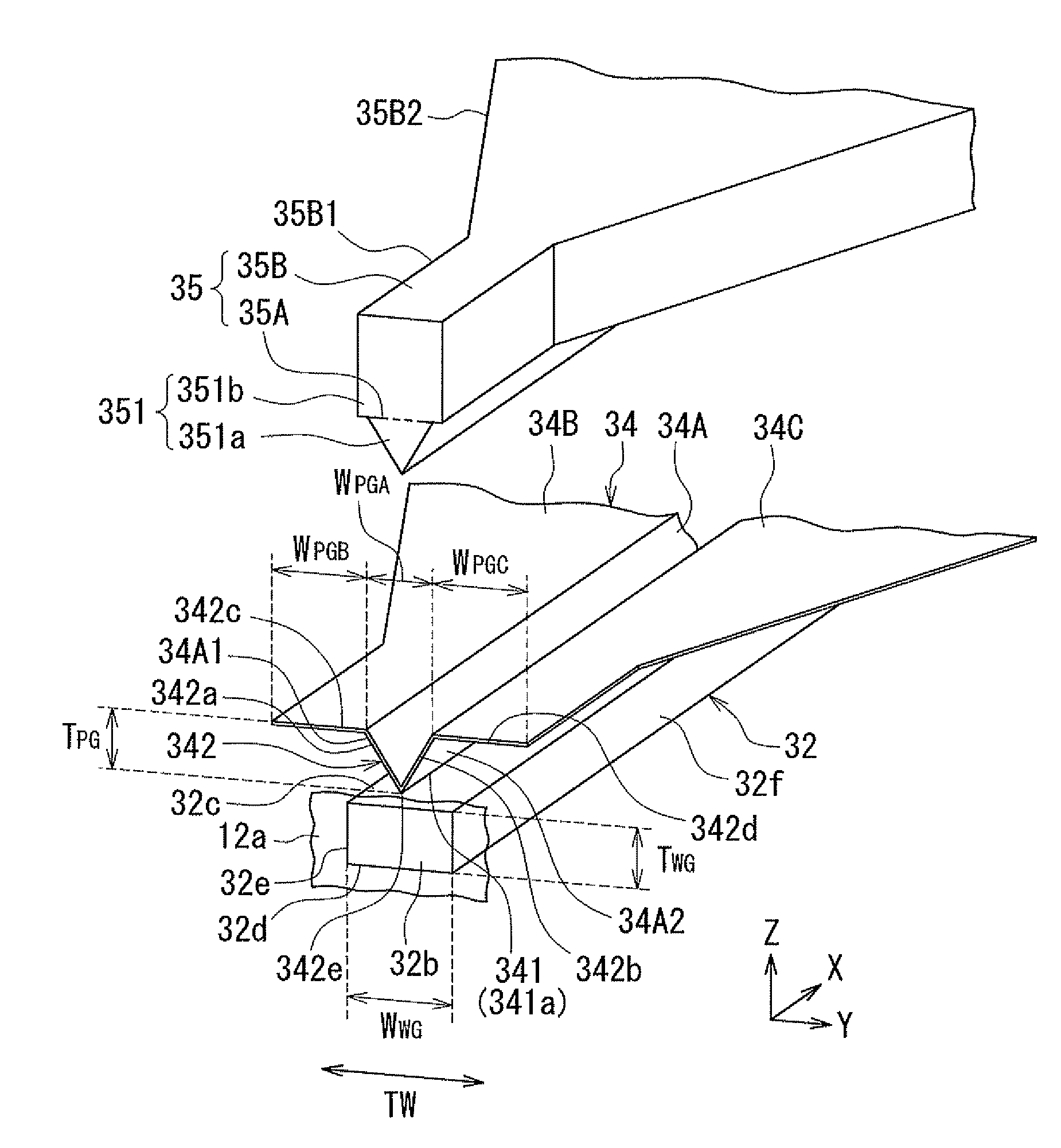
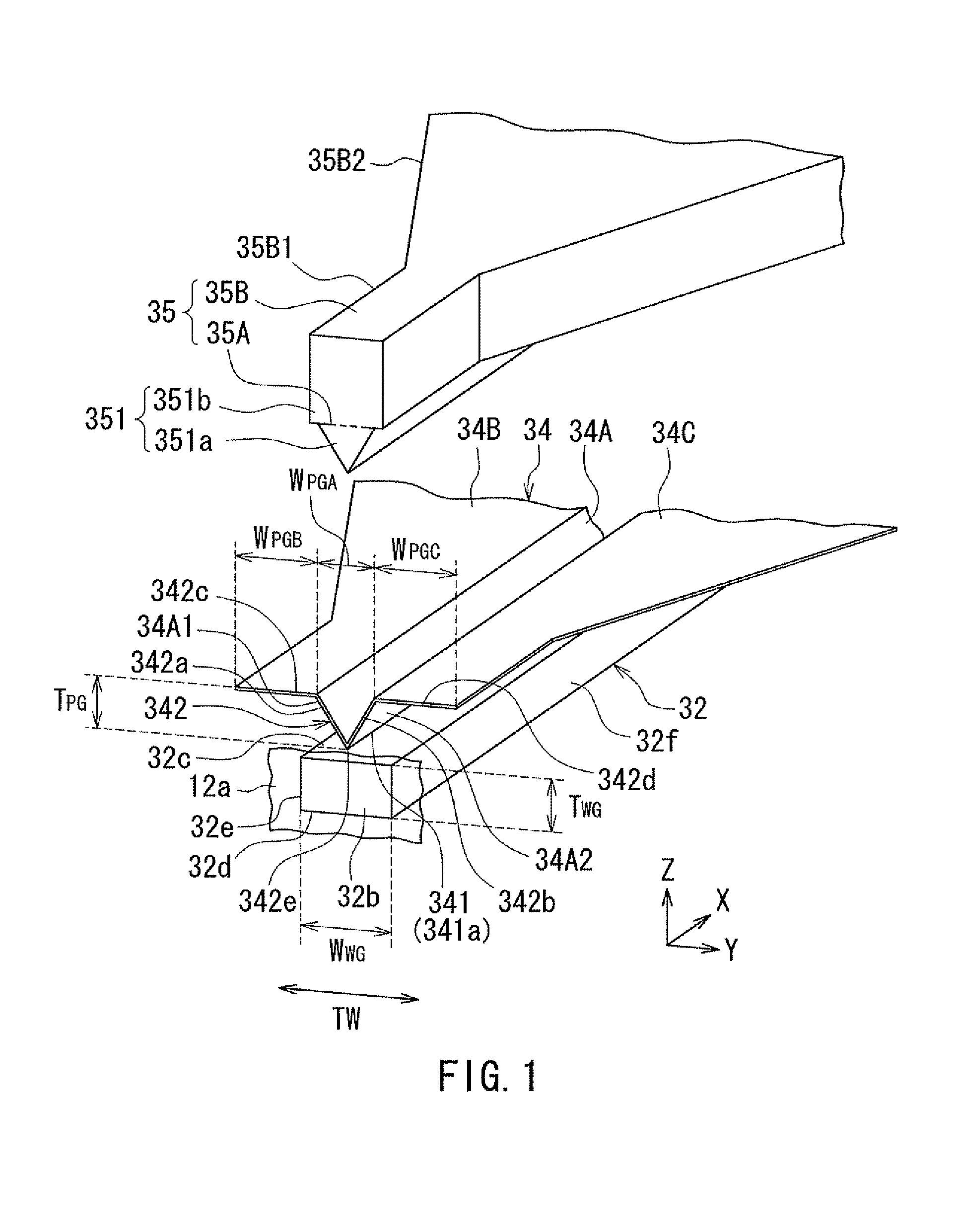
[0179]A second embodiment of the invention will now be described with reference to FIG. 20 and FIG. 21. FIG. 20 is a perspective view showing the core of the waveguide, the plasmon generator, and the magnetic pole of the thermally-assisted magnetic recording head according to the present embodiment. FIG. 21 is a plan view showing the plasmon exciting part of the plasmon generator shown in FIG. 20 as viewed from above. The plasmon generator 34 of the present embodiment has a first portion 34D and a second portion 34E, instead of the V-shaped portion 34A of the first embodiment. The first portion 34D has an end face located in the medium facing surface 12a. The second portion 34E is located farther from the medium facing surface 12a than is the first portion 34D, such that the second portion 34E is continuous with the first portion 34D. In FIG. 20, the border between the first portion 34D and the second portion 34E is shown by a chain double-dashed line.

[0180]The first portion 34D has...

third embodiment

[0206]A third embodiment of the invention will now be described with reference to FIG. 22 and FIG. 23. FIG. 22 is a front view showing a part of the medium facing surface of the head unit of the thermally-assisted magnetic recording head according to the present embodiment. FIG. 23 is a cross-sectional view showing the core of the waveguide, the plasmon generator, and the magnetic pole of the thermally-assisted magnetic recording head according to the present embodiment. The thermally-assisted magnetic recording head according to the present embodiment has a plasmon generator 84 and a magnetic pole 85, instead of the plasmon generator 34 and the magnetic pole 35 of the first embodiment. The plasmon generator 84 is made of the same material as that of the plasmon generator 34 of the first embodiment. The magnetic pole 85 is made of the same material as that of the magnetic pole 35 of the first embodiment.

[0207]The plasmon generator 84 has an outer surface that includes a plasmon exci...


PUM

PropertyMeasurementUnit
lengthaaaaaaaaaa
wavelengthaaaaaaaaaa
emittable wavelength rangeaaaaaaaaaa

Abstract

An outer surface of a plasmon generator includes: a plasmon exciting part that faces an evanescent light generating surface with a predetermined distance therebetween; and a front end face located in a medium facing surface. The plasmon generator has: first and second sidewall parts that are connected to the plasmon exciting part and increase in distance from each other with increasing distance from the plasmon exciting part; and at least one extended portion connected to an edge of at least one of the first and second sidewall parts opposite from the plasmon exciting part. A magnetic pole has a portion interposed between the first and second sidewall parts. The front end face includes first and second portions lying at ends of the first and second sidewall parts and connected to each other into a V-shape. An end face of the magnetic pole has a portion interposed between the first and second portions of the front end face.

Description

BACKGROUND OF THE INVENTION[0001]1. Field of the Invention[0002]The present invention relates to a thermally-assisted magnetic recording head including a plasmon generator for use in thermally-assisted magnetic recording where a magnetic recording medium is irradiated with near-field light to lower the coercivity of the magnetic recording medium for data writing.[0003]2. Description of the Related Art[0004]Recently, magnetic recording devices such as magnetic disk drives have been improved in recording density, and thin-film magnetic heads and magnetic recording media of improved performance have been demanded accordingly. Among the thin-film magnetic heads, a composite thin-film magnetic head has been used widely. The composite thin-film magnetic head has such a structure that a read head including a magnetoresistive element (hereinafter, also referred to as MR element) intended for reading and a write head including an induction-type electromagnetic transducer intended for writing...

Claims


Application Information

Patent Timeline
Patent Type & Authority Patents(United States)
IPC IPC(8): G11B11/00
CPCG02B5/008G02B27/56G11B5/3116G11B5/314G11B5/3163G11B5/6088G11B2005/0021
Inventor MIYAUCHI, DAISUKEROPPONGI, TETSUYATANAKA, KOSUKEAOKI, SUSUMUKURIHARA, KATSUKI
Owner TDK CORPARATION
Why Eureka
Try Eureka