Turbine airfoil with dual wall formed from inner and outer layers separated by a compliant structure

a technology of compliant structure and turbine airfoil, which is applied in the direction of liquid fuel engines, vessel construction, marine propulsion, etc., can solve problems such as the likelihood of failure, and achieve the effect of preventing the accumulation of stress and reducing stress formation

Inactive Publication Date: 2011-12-20
SIEMENS ENERGY INC
View PDF22 Cites 22 Cited by
  • Summary
  • Abstract
  • Description
  • Claims
  • Application Information

AI Technical Summary

Benefits of technology

[0006]This invention relates to a turbine airfoil usable in a turbine engine with a cooling system and a compliant dual wall configuration configured to enable thermal expansion between inner and outer layers while eliminating stress formation. The compliant dual wall configuration may be formed from a dual wall that is formed from inner and outer layers separated by a compliant structure. The compliant structure may be configured such that the outer layer may thermally expand without limitation by the inner layer. The compliant structure may be formed from materials that enable the outer layer, which is exposed to the hot gas path, to thermally expand independent of the inner layer, thereby preventing the accumulation of stress within the dual wall.
[0007]The turbine airfoil may be formed from a generally elongated hollow airfoil formed from an outer dual wall having a leading edge, a trailing edge, a pressure side, a suction side, an outer endwall at a first end, an inner endwall at a second end opposite the first end, and a cooling system positioned in the generally elongated airfoil formed by the outer dual wall. The dual wall may be formed from an outer layer and an inner layer separated from the outer layer by a compliant structure that allows the outer and inner layers to move relative to each other thereby reducing the buildup of stress between the layers. The compliant structure may be formed from a plurality of pedestals attached to the outer layer and inner layers and extending nonorthogonally and nonparallel between the two layers. The pedestals may be equally spaced and may include feet facilitating attachment to the outer and inner layers. In one embodiment, the pedestals may be positioned generally parallel with each other and at least one of the pedestals may include a first foot attached to a first end of the pedestal and extending in a first direction aligned with the contact surface of the outer layer and a second foot attached to a second end of the pedestal and extending in a second direction aligned with the contact surface of the inner layer. At least a portion of the pedestals may be positioned at different angles relative to the inner layer thereby creating different thermal growth in distance between the inner layer and the outer layer such that a distance between the outer and inner layers differs along a length of the outer and inner layers.
[0009]An advantage of this invention is that the compliant structure positioned between the inner and outer layers enables the outer layer to thermally expand greater than the inner layer without the buildup of stress.
[0010]Another advantage of this invention is that the outer layer may move laterally in a direction that is generally aligned with the outer layer.
[0011]Still another advantage of this invention is that the nonlinear shaped pedestals enable customized thermal expansion of the outer layer in the lateral and radial directions.
[0012]Another advantage of this invention is that the pedestals provide cooling channels between the inner and outer layers that enable cooling fluids to be passed therethrough.

Problems solved by technology

In addition, turbine vanes and blades often contain cooling systems for prolonging the life of the vanes and blades and reducing the likelihood of failure as a result of excessive temperatures.

Method used


Image

  • Turbine airfoil with dual wall formed from inner and outer layers separated by a compliant structure
  • Turbine airfoil with dual wall formed from inner and outer layers separated by a compliant structure
  • Turbine airfoil with dual wall formed from inner and outer layers separated by a compliant structure

Examples


Embodiment Construction

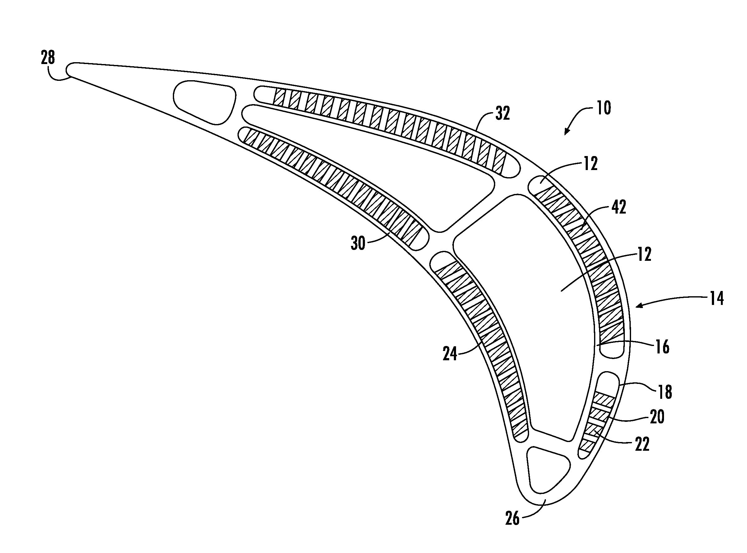
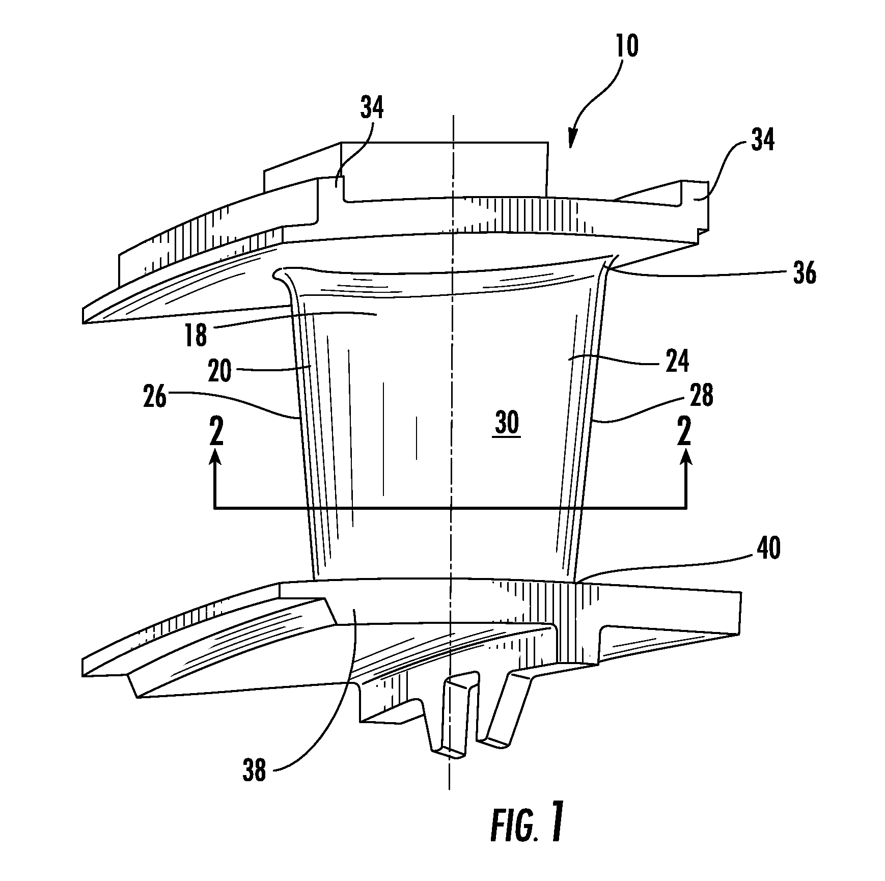
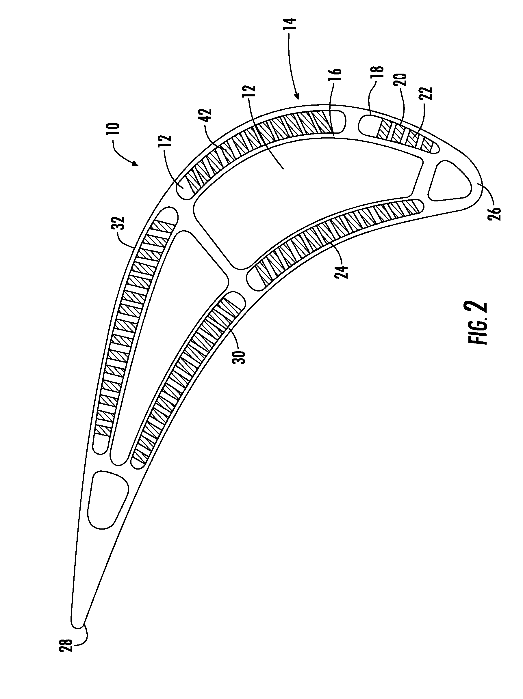
[0025]As shown in FIGS. 1-10, this invention is directed to a turbine airfoil 10 usable in a turbine engine with a cooling system 12 and a compliant dual wall configuration 14 configured to enable thermal expansion between inner and outer layers 16, 18 while eliminating stress formation. The compliant dual wall configuration 14 may also be used in other turbine components 10, such as, but not limited to, transitions, ring segments, shrouds and other hot gas path structures. The compliant dual wall configuration 14 may be formed a dual wall 20 formed from inner and outer layers 16, 18 separated by a compliant structure 22. The compliant structure 22 may be configured such that the outer layer 18 may thermally expand without limitation by the inner layer 16. The compliant structure 22 may be formed from materials that enable the outer layer 18, which is exposed to the hot gas path, to thermally expand independent of the inner layer 16, thereby preventing the accumulation of stress wit...


PUM


Abstract

A turbine airfoil usable in a turbine engine with a cooling system and a compliant dual wall configuration configured to enable thermal expansion between inner and outer layers while eliminating stress formation is disclosed. The compliant dual wall configuration may be formed a dual wall formed from inner and outer layers separated by a compliant structure. The compliant structure may be configured such that the outer layer may thermally expand without limitation by the inner layer. The compliant structure may be formed from a plurality of pedestals positioned generally parallel with each other. The pedestals may include a first foot attached to a first end of the pedestal and extending in a first direction aligned with the outer layer, and may include a second foot attached to a second end of the pedestal and extending in a second direction aligned with the inner layer.

Description

STATEMENT REGARDING FEDERALLY SPONSORED RESEARCH[0001]Development of this invention was supported in part by the United States Department of Energy, Contract No. DE-FC26-05NT42644. Accordingly, the United States Government has certain rights in this invention.FIELD OF THE INVENTION[0002]This invention is directed generally to turbine airfoils, and more particularly to hollow turbine airfoils having cooling channels for passing fluids, such as air, to cool the airfoils.BACKGROUND[0003]Typically, gas turbine engines include a compressor for compressing air, a combustor for mixing the compressed air with fuel and igniting the mixture, and a turbine blade assembly for producing power. Combustors often operate at high temperatures that may exceed 2,500 degrees Fahrenheit. Typical turbine combustor configurations expose turbine vane and blade assemblies to these high temperatures. As a result, turbine vanes and blades must be made of materials capable of withstanding such high temperature...

Claims


Application Information

Patent Timeline
Patent Type & Authority Patents(United States)
IPC IPC(8): F01D5/18
CPCF01D5/147F01D5/18
Inventor CAMPBELL, CHRISTIAN X.MORRISON, JAY A.
Owner SIEMENS ENERGY INC
Why Eureka
Try Eureka