Method for measuring the radial velocity of a target with a doppler radar

a radar and target technology, applied in the field of radars, can solve the problems of ambiguity in range, limited transmission power capability of pulsed radars, and the need for radar beams to spend longer time on targets

Inactive Publication Date: 2011-12-20
THALES NEDERLAND BV
View PDF18 Cites 20 Cited by
  • Summary
  • Abstract
  • Description
  • Claims
  • Application Information

AI Technical Summary

Benefits of technology

[0032]An embodiment of the present invention aims to provide a processing technique that is applicable to a pulse compression waveform with multi-carrier structure, which includes an OFDM waveform. The proposed waveform and the corresponding processing technique measures the radial velocity using a pulse train, without the need for using consecutive pulse trains with different RF or different pulse repetition frequencies to solve the radial velocity ambiguity. An important idea of the processing technique is based on the deteriorating pulse compression gain due to the Doppler effect manifesting itself as RF frequency shift.

Problems solved by technology

Pulsed radars have limited transmission power capability due to the low duty cycle required for unambiguous and high-resolution range measurement.
This, in turn, requires the radar beam to spend longer time on target.
Shorter compression pulses correspond to higher pulse repetition frequency if the peak and average power levels are to be kept constant, which in turn causes ambiguity in range.
U.S. Pat. No. 6,392,588, which discloses the multicarrier MCPC waveform, does not address the radial velocity resolution, ambiguity arising from the use of the pulsed waveform, the deterioration of pulse compression due to the Doppler effect and possible solutions to the Doppler intolerance of the pulse compression.
Furthermore, no structure to implement the Doppler shifted filters is proposed.
Such pulses have very high Peak to Average Power Ratio (PAPR), leading to very low average transmitted power and possibly distortion due to the amplifier entering the saturation region.
Multi-path effects introduce inter-symbol interference and inter-carrier interference, leading to high bit error rate in communications.

Method used


Image

  • Method for measuring the radial velocity of a target with a doppler radar
  • Method for measuring the radial velocity of a target with a doppler radar
  • Method for measuring the radial velocity of a target with a doppler radar

Examples


Embodiment Construction

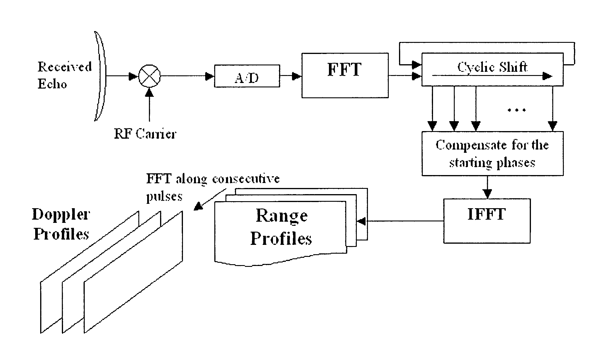
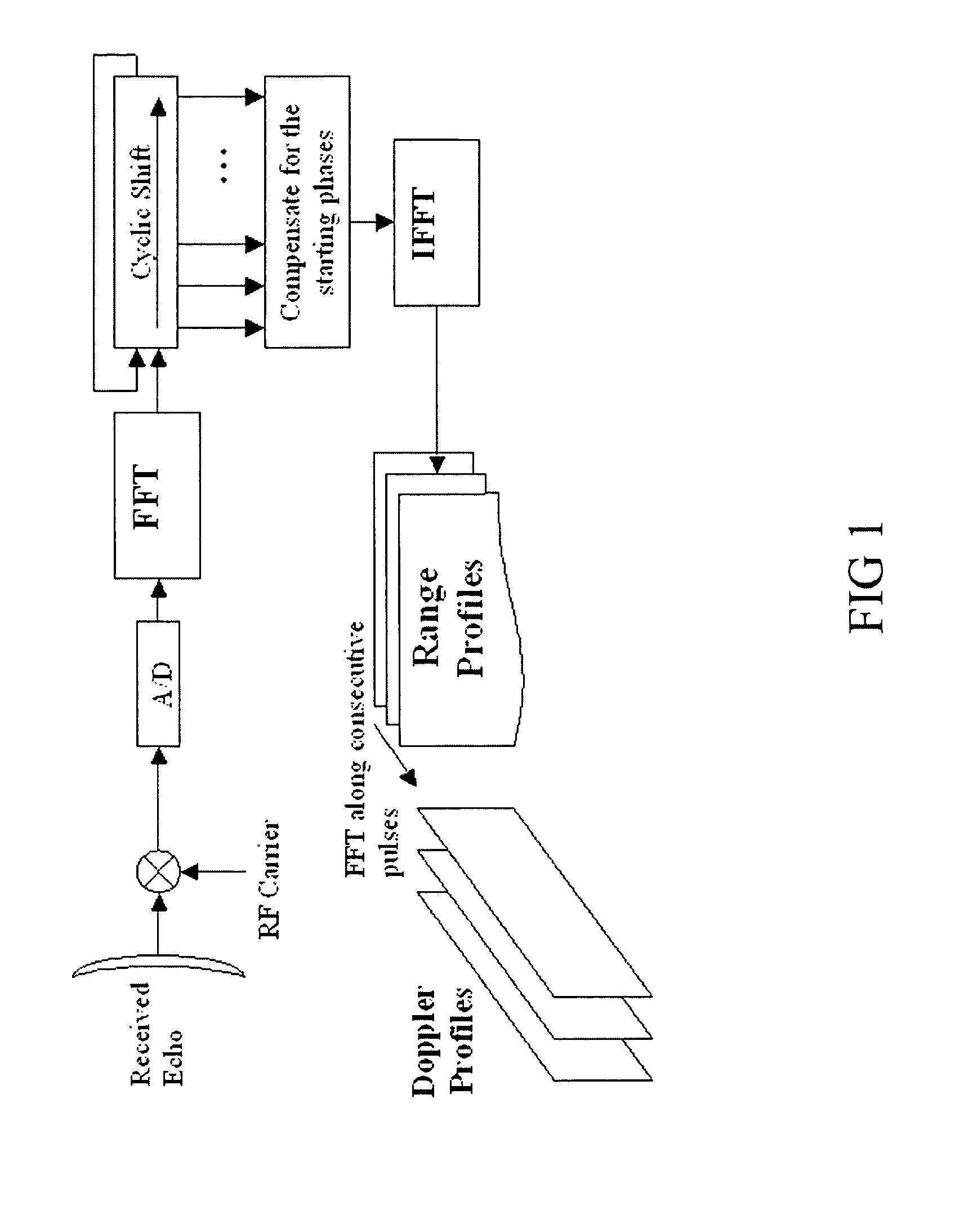
[0052]The signal structure utilizes multiple carriers forming the OFDM waveform. The OFDM waveform p(n) is the sum of carriers pk(n), presented in discrete form as

[0053]p⁡(n)=∑m=0N-1⁢xm⁢exp⁢{jϕm}⁢exp⁢{j2π⁢⁢m⁢⁢Δ⁢⁢f⁡(nN-1)⁢T},(1)

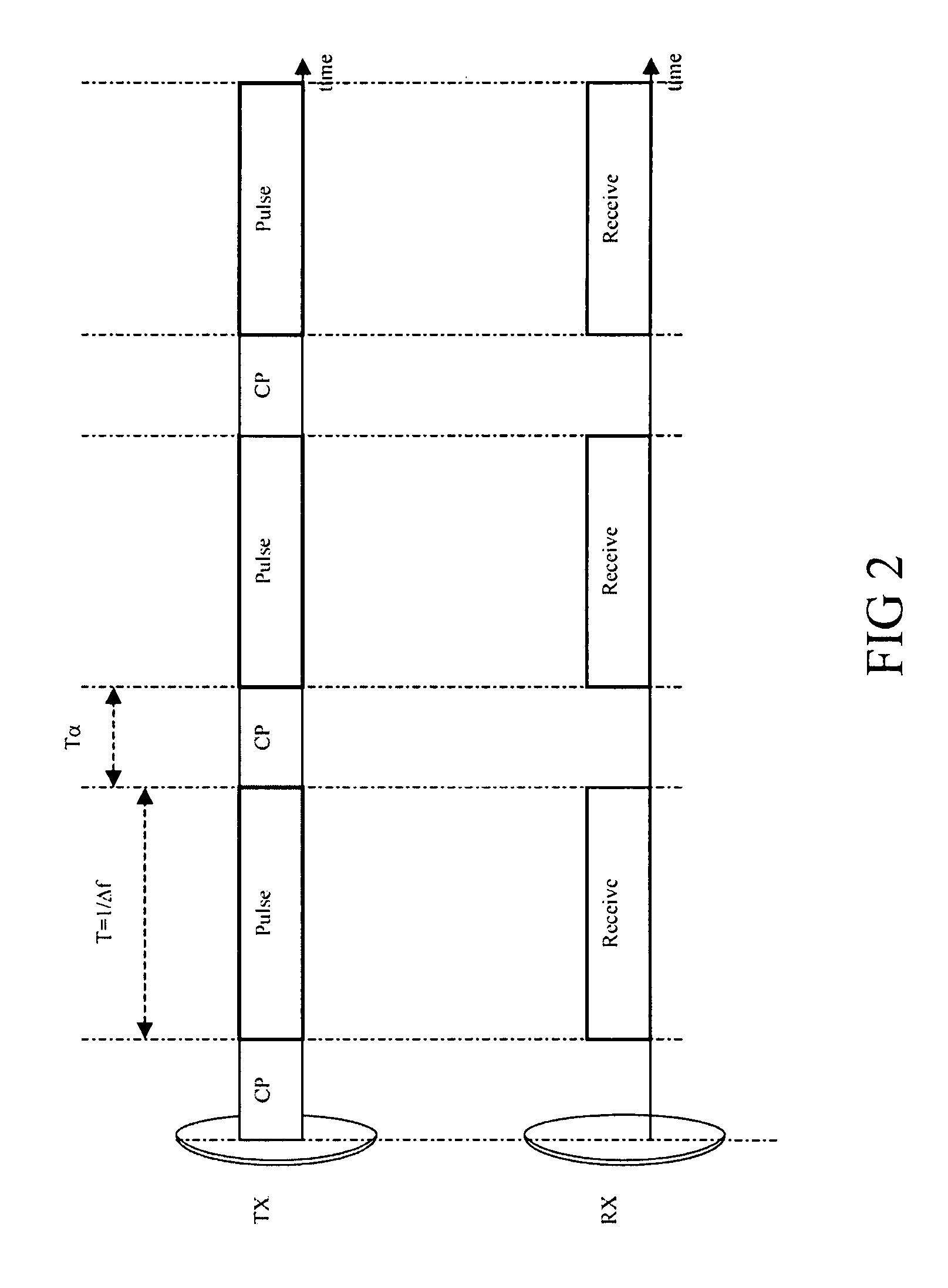
where xm exp{jφm} is the amplitude and phase of the complex symbol modulating the carrier m, N is the number of carriers, and T=1 / Δf is the symbol duration with Δf the carrier spacing. Thus, carrier m has amplitude xm and initial phase φm. The complex symbols modulating each carrier can be considered as being transmitted in parallel. The processing method presented here imposes no limitations on the choice of the phases of the symbols, covering all phase coding schemes as applied in radar and communication applications.

[0054]The carriers are said to be orthogonal under the relation:

[0055]ck=∑n=0N-1⁢∑m=0N-1⁢xm⁢exp⁢{jϕm}⁢exp⁢{j2π⁢⁢m⁢⁢Δ⁢⁢f(nN-1)⁢T}⁢exp⁢{-j2⁢⁢π(nN-1)⁢k}.(2)

[0056]The mathematical relationship between the orthogonal carriers hold only when the wavef...


PUM


Abstract

An embodiment of the invention includes a step of transmitting an OFDM waveform including several frequency carrier signals transmitted simultaneously, the frequency carrier signals being coded in order to improve the Doppler response. An embodiment of the invention includes a step of receiving the echoed waveform from the target. The initial phase of each frequency carrier signal is recovered from the echoed waveform. The recovered initial phase of each frequency carrier signal is cyclically shifted in order to compensate for the Doppler effect and subsequently decoded. A compressed pulse is synthesized from the decoded initial phases.

Description

CROSS-REFERENCE TO RELATED APPLICATIONS[0001]The present application claims the benefit of Netherlands Patent Application Serial No. 1035066, filed Feb. 22, 2008 which is hereby incorporated by reference in its entirety.FIELD OF THE INVENTION[0002]The invention is in the field of radar and similar ranging techniques, which detect remote targets and determine target parameters such as range and radial velocity. The invention relates to the signal structure and associated processing technique that estimates the target range and radial velocity.BACKGROUND OF THE INVENTION[0003]The remote detection systems determine target parameters such as range and radial velocity by transmitting a waveform and comparing, through various processing methods, the transmitted waveform and the received signal that is echoed from the target. The range of the target is determined through the measurement of the time of arrival of the echo and the radial velocity is measured from the Doppler effect, which is...

Claims


Application Information

Patent Timeline
Patent Type & Authority Patents(United States)
IPC IPC(8): G01S7/28G01S7/32G01S13/00
CPCG01S13/28G01S13/582H04L27/2601H04L27/2607G01S13/24G01S2007/2883G01S7/2883
Inventor TIGREK, RECEP FIRATDE HEIJ, WILHELMUS JOHANNES
Owner THALES NEDERLAND BV
Why Eureka
Try Eureka