Non-contact damage-free ultrasonic cleaning of implanted or natural structures having moving parts and located in a living body

a technology of implanted or natural structures and living bodies, applied in the field of prosthetic heart valves, can solve problems such as potential interference, and achieve the effect of reducing the intensity of the sound

Inactive Publication Date: 2011-12-27
TOSAYA CAROL A +1
View PDF21 Cites 13 Cited by
  • Summary
  • Abstract
  • Description
  • Claims
  • Application Information

AI Technical Summary

Benefits of technology

[0019]In accordance with the present invention, ultrasonic, sonic or vibratory energy, delivered non-invasively, minimally invasively or invasively (e.g., surgically), is utilized to preferably provide direct cleaning action at or to the location of an implanted artificial or bioprosthetic device, such as a prosthetic heart valve, or a natural bodily member or organ with a naturally moving, actuating or distending part or portion with undesirable deposits of at least some amount thereon or therein. Such ultrasound energy may be aided by the use of a drug in association or cooperation with the acoustic irradiation. If a drug is used, the ultrasound may enhance the performance of that drug via its acoustic and / or thermal attributes. Alternatively, or in addition, the drug may make it easier to achieve deposit removal by destabilizing or softening such deposits. Such a drug might be given at least one of before, during or after the acoustic therapy.
[0040]Finally, the present inventors teach that the cleaning acoustics may be directed at a portion of the implant, member or organ such that the acoustic intensity is maximized at desired locations or such that other fragile portions of the implant are avoided by the cleaning processes.

Problems solved by technology

The deposits to be removed or eroded interfere or potentially interfere with at least one of (a) any designed function of the implanted device, (b) any natural function of the natural bodily member or organ, or (c) any circulatory system process necessary for normal healthy living.

Method used


Image

  • Non-contact damage-free ultrasonic cleaning of implanted or natural structures having moving parts and located in a living body
  • Non-contact damage-free ultrasonic cleaning of implanted or natural structures having moving parts and located in a living body

Examples


Embodiment Construction

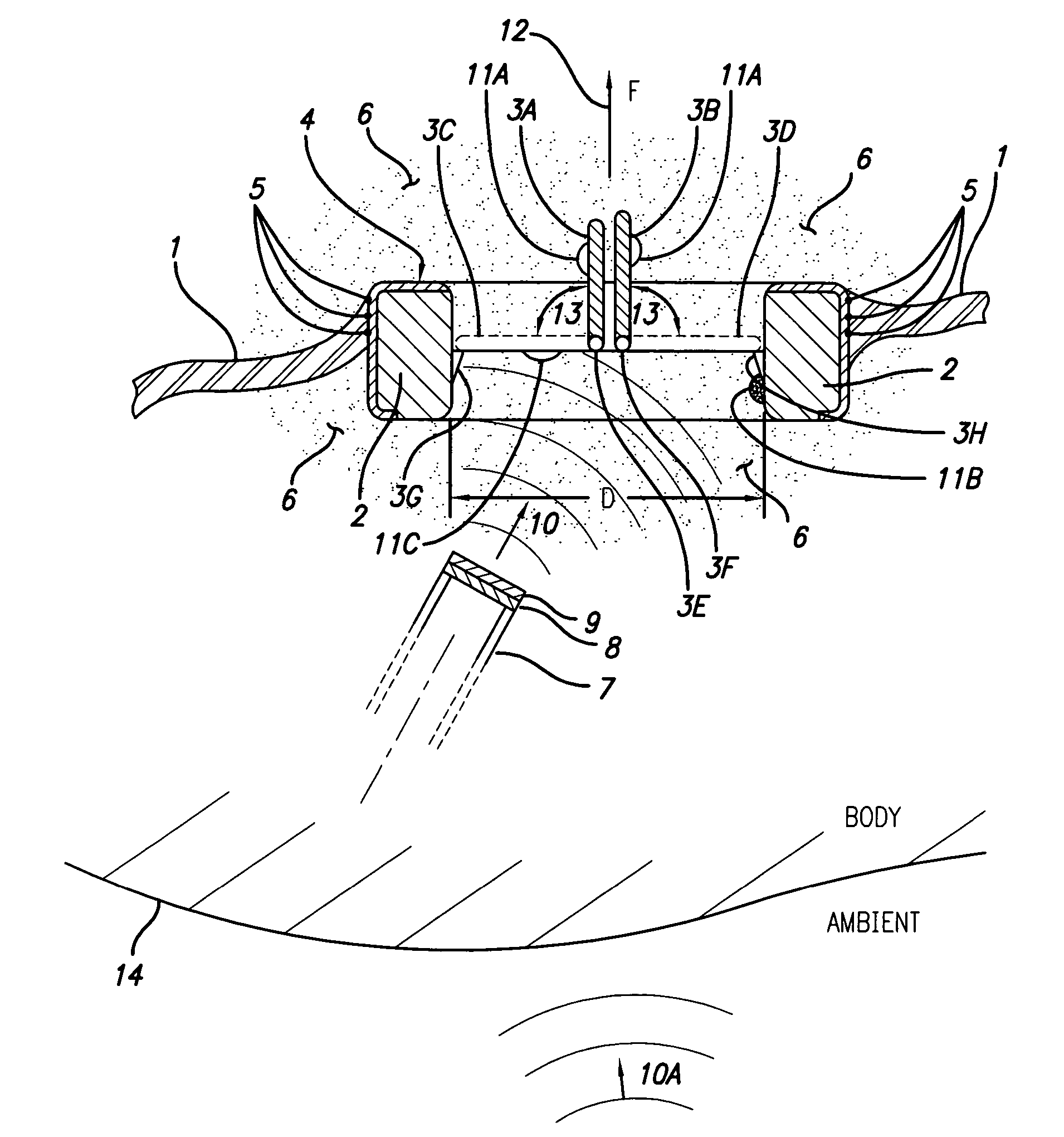
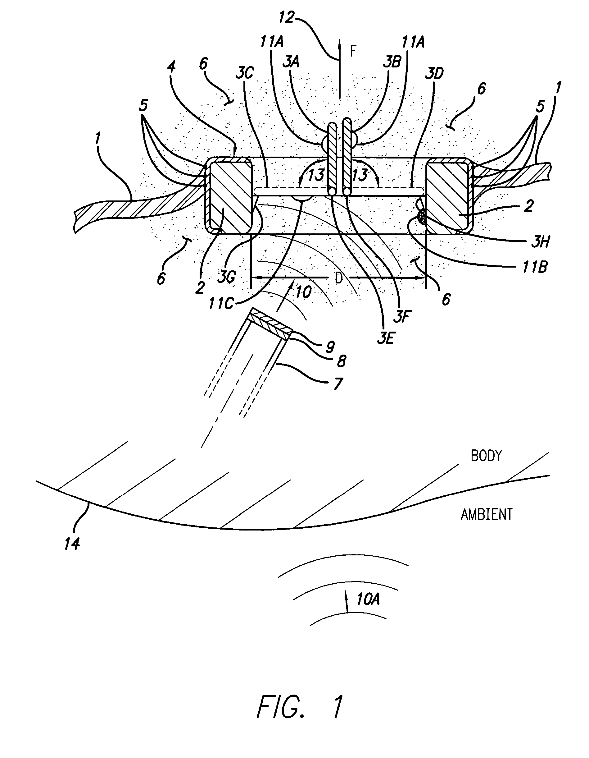
[0042]Moving directly now to the Figure, there is shown (not to scale) an artificial prosthetic heart valve 2 mounted in cardiac tissue 1 defining a chamber of the heart. In fact, item 2 is the known typical annular valve body of such a valve. Typically, body 2 is made of pyrolytic carbon or titanium. Typically, the valve 2 will have one or more swinging leaflets or occluders 3A and 3B as shown. Note that in the Figure, normal blood flow F is upwards in the direction of flow arrow 12. Valve 2 acts as a check valve preventing downwards flow by closing its leaflets 3A and 3B to the respective closed and seated phantom positions 3C and 3D. The leaflets swing as indicated by arrows 13. Also typically, leaflets 3A and 3B will swing upon hinged pivots of the type 3E and 3F. The axis of such pivoting is normal to the plane of the drawing. Typically, valves will have a fabric covering 4, which allows the use of sutures 5 to attach the valve 2 to the cardiac tissue or annulus 1. Blood 6 is s...


PUM


Abstract

Ultrasonic, sonic or vibratory energy, delivered non-invasively, minimally invasively or invasively (e.g. surgically), is utilized to provide direct cleaning action at or to the location of the implanted device such as a prosthetic heart valve with undesirable deposits of at least some amount thereon or therein. Such ultra-sound energy may be aided by the use of a drug in association or cooperation with the acoustic irradiation. The “cleaning” acoustic energy may optionally be delivered under the guidance of an imaging modality and may be delivered in a timed or gated manner such that the valve occluders or leaflets are in a preferred position (assuming they are functioning) during exposures.

Description

CROSS-REFERENCE TO RELATED APPLICATION[0001]The present application claims priority from provisional application Ser. No. 60 / 463,918, filed Apr. 17, 2003.TECHNICAL FIELD[0002]The present application is directed generally to prosthetic heart valves, and, more particularly, to cleaning such heart valves, preferably in situ, with acoustic energy.BACKGROUND ARTBackground Discussion[0003]Prosthetic heart valves are probably one of the most well-known implanted medical devices and are installed in an ailing human heart for the purpose of correcting cardiac valvular dysfunctions of various types. Such valves are made either of artificial biocompatible engineering materials, such as pyrolytic carbon, titanium, and silicone, or are fashioned out of donor tissues or actual valves or other tissues sourced from pigs, cattle or human donors.[0004]Particularly for cardiac valves made of such artificial engineering materials, experience has shown that over time, even with the administration of ant...

Claims


Application Information

Patent Timeline
Patent Type & Authority Patents(United States)
IPC IPC(8): A61B17/20A61B17/22A61B19/00
CPCA61B17/22004A61B19/5225A61B2017/00243A61B2017/22098A61B90/37
Inventor TOSAYA, CAROL A.SLIWA, JR., JOHN W.
Owner TOSAYA CAROL A
Why Eureka
Try Eureka