Hermetic seal for discrete opening in disk drive housing

a disk drive and discrete sealing technology, which is applied in the direction of casings/cabinets/drawers, instruments, casings/cabinets/drawers details, etc., can solve the problems of affecting the registration of the read/write element relative to the track, increasing the difficulty of the read/write head to accurately read and write information to and from the narrowing track, and increasing the difficulty of maintaining the read/write element over the track at the optimal position for accurate data transfer

Active Publication Date: 2012-01-03
SEAGATE TECH LLC
View PDF14 Cites 12 Cited by
  • Summary
  • Abstract
  • Description
  • Claims
  • Application Information

AI Technical Summary

Problems solved by technology

However, decreasing the width of tracks makes it more difficult for the read / write heads to accurately read and write information to and from the narrowing tracks.
Not only is it difficult to physically position the read / write element over a narrow width track, but it is increasingly difficult to maintain the read / write element over the track at an optimal position for accurate data transfer.
Air turbulence created by the spinning disks, disk flutter and spindle vibrations, temperature and altitude can all adversely effect registration of the read / write element relative to the tracks.
Moreover, increasing the speed of the rotating disks to achieve increased data access times increases air turbulence, which increases misregistration between the read / write element and the tracks on the storage disks (track misregistration or TMR).
Accuracy can be further adversely affected if the read / write heads are not maintained within an optimum height range above the surface of the storage disk.
However, since the disk rotates many thousands of revolutions per minute or more, continuous direct contact between the slider and the recording medium can cause unacceptable wear on these components.
Excessive wear on the recording medium can result in the loss of data, among other things.
Excessive wear on the slider can result in contact between the read / write transducer and the disk surface resulting, in turn, in failure of the transducer, which can cause catastrophic failure.
In non-contact disk drives there are also limitations on how close a read / write element may be to the surface of a disk.
These factors, as well as air turbulence, disk flutter and spindle vibration, can cause the read / write element flying height to vary or even cause the read / write element to contact the spinning disk.
Such seals are not designed to prevent internal air and other gases from exiting through the seal and out of the drive.
Some low density gases also have greater thermal conductivity, which results in better motor efficiencies and therefore lower power consumption for a given performance level.
Despite these advantages, low density gas-filled drives have not been commercially successful.
It has been difficult to prevent the low density gas from escaping from the sealed drive environment.
Conventional rubber seals used in air-filled drives are inadequate at preventing leakage of low density gas due to the smaller atom size of low density gases, such as helium, compared to air.
Thus, over time, the necessary threshold quantity of low density gas may be lost within the drive environment and may or may not be replaced with ambient air.
As the low density gas leaks out of a drive and is replaced by air, the drive is subject to undesirable operational effects possibly leading to unacceptable error rates and / or failure of the drive.
For example, the increased concentration of air may increase the turbulent forces on the heads due to the increased drag forces within the drive which may further cause the heads to fly at too great a distance above the disks and potentially increasing instances of read / write errors.
If the low density gas leaks from the sealed environment over time and is not replaced by ambient air, problems will occur such as the heads flying at a distance too close or in contact with the disks, thereby increasing instances of read / write errors as well as damage to the disk surface and head and higher operating temperatures due to a reduction in conduction cooling.
Each creates a reliability risk.
The risk of unanticipated failures due to inadequate amounts of low density gas within the drive is a draw back to low density gas-filled drives.
Indeed, data stored within the drive may be irretrievably lost if the drive fails due to the loss of the low density gas environment.

Method used


Image

  • Hermetic seal for discrete opening in disk drive housing
  • Hermetic seal for discrete opening in disk drive housing
  • Hermetic seal for discrete opening in disk drive housing

Examples


Embodiment Construction

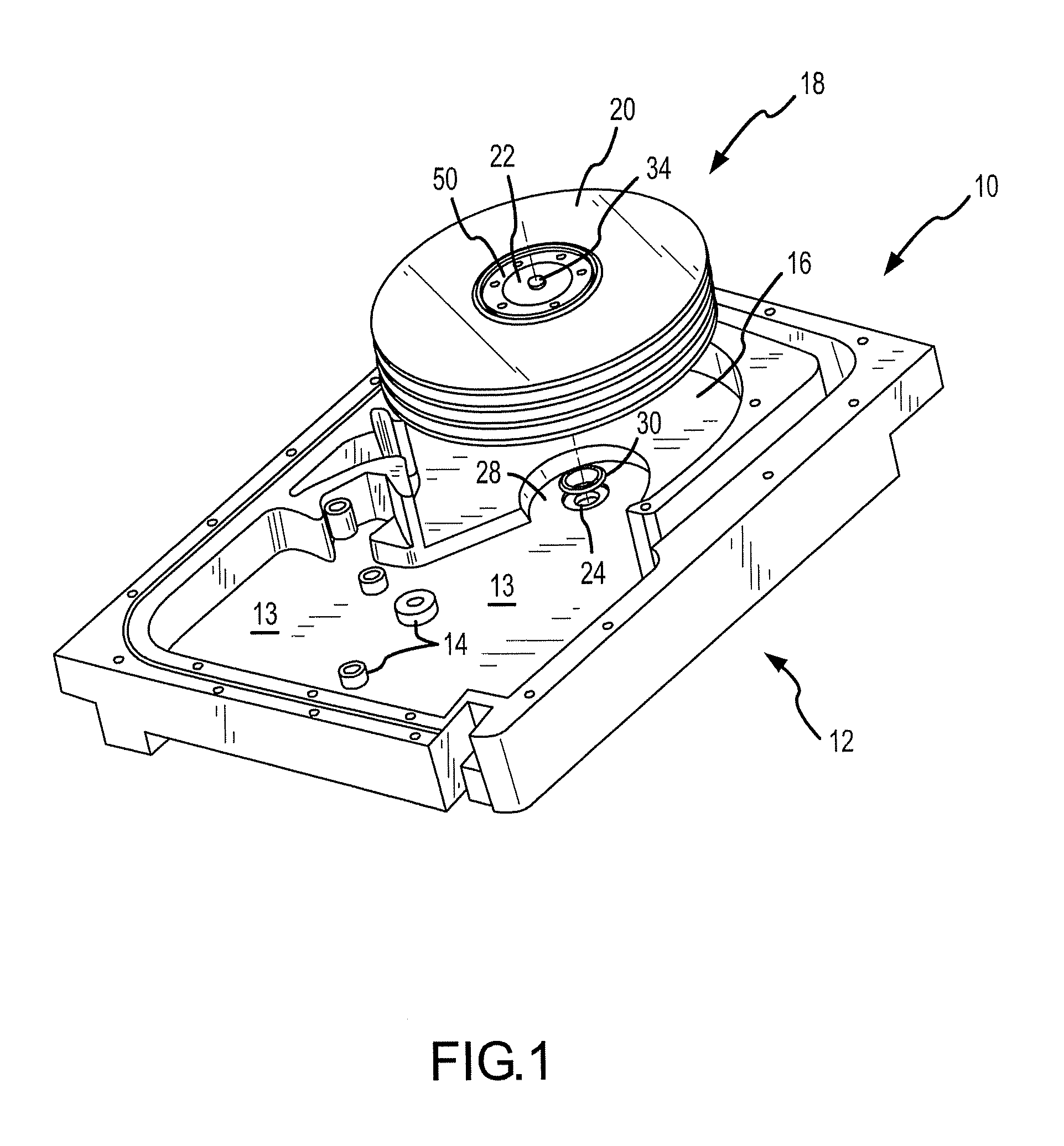
[0022]FIG. 1 illustrates one part of the housing assembly 10 of a disk drive, namely, the base plate 12. As shown, the base plate is a rectangular-shaped member having an interior portion thereof that forms a cavity 13 to house the components of the disk drive. Additionally, various protruding features 14 may be found within the cavity 13 of the base plate 12 to accommodate attachment of the components of the disk drive. One portion 16 of the cavity 13 includes an area to receive a disk pack 18. The disk pack 18 may include a plurality of data disks 20 stacked over a hub 22, and a disk clamp 50 (also see FIG. 5) is secured over an upper end of the hub 22.

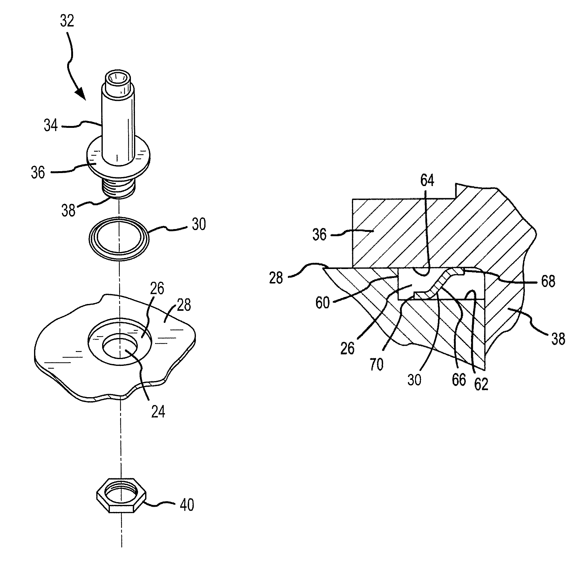
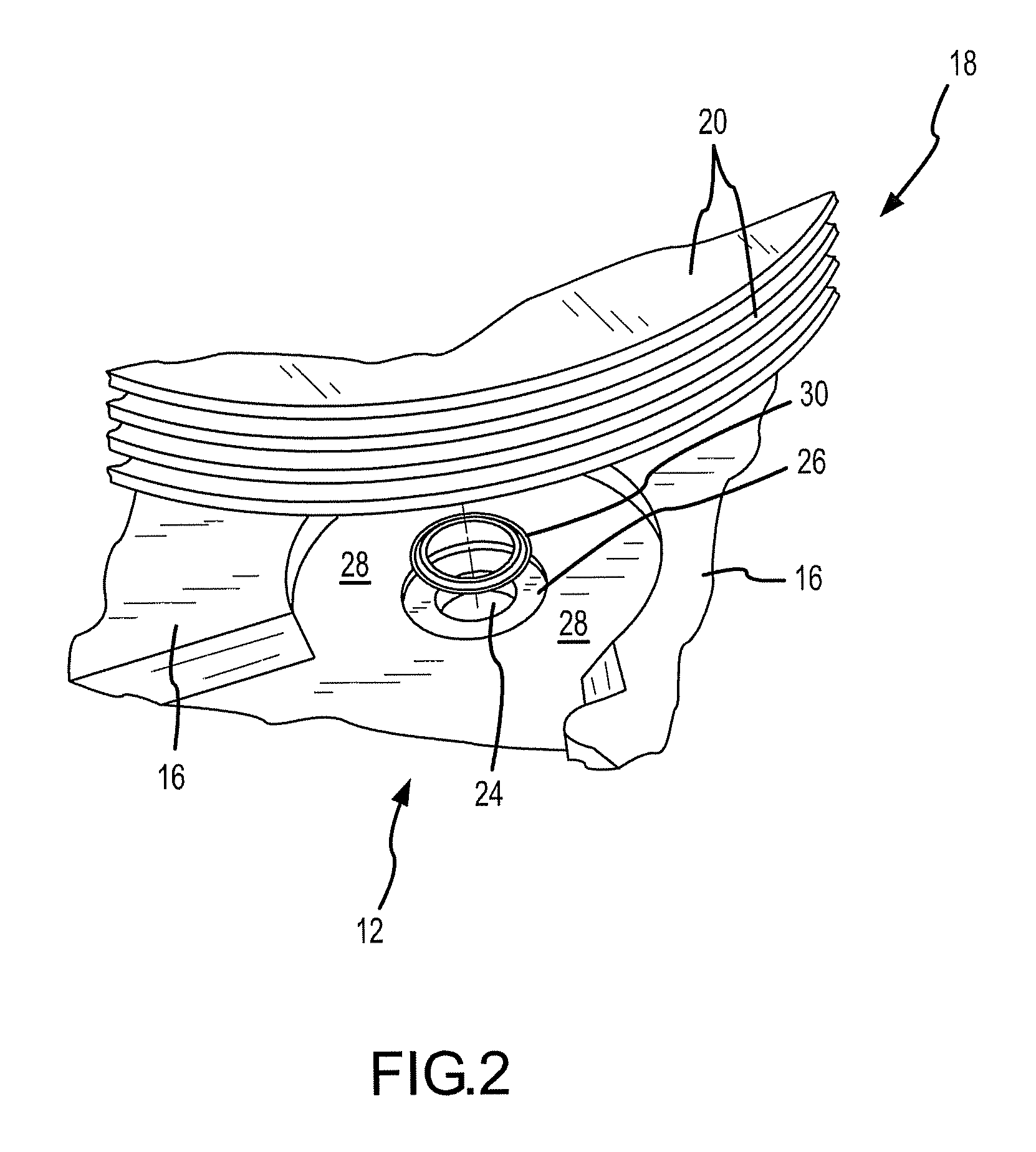
[0023]As shown in FIG. 2, the base plate 12 may include an opening 24 that receives the spindle shaft 32 (FIG. 3). Directly adjacent the opening 24 and formed concentrically around the opening is a recess 26. The exposed surface of the cavity 13 around the recess 26 is shown as surface 28.

[0024]Referring specifically to FIG. 3, the ...


PUM

PropertyMeasurementUnit
diameteraaaaaaaaaa
temperatureaaaaaaaaaa

Abstract

A hermetic seal is provided for sealing a discrete opening in a disk drive base plate. The hermetic seal comprises a sealing gasket that is disposed between planar facing surfaces of a component inserted through the opening and a recess formed on the interior of the base plate. As the gasket is compressed, a deformable plating applied to the gasket deforms and flows to fill microscopic voids that may be found in the abutting planar surfaces. Required access to the disk drive through the opening may be made in a rework process without destroying the seal. To seal the opening of the drive again, the sealing gasket is simply recompressed between the planar abutting surfaces. The invention also comprises a method by which to seal the castings of the disk drive housing, to include the base plate and top cover the disk drive. The method generally includes a two-time resin impregnation process to fill exposed pores on the surface of the castings.

Description

CROSS REFERENCE TO RELATED APPLICATION[0001]Priority is claimed from U.S. Provisional Patent Application No. 60 / 738,879, filed on Nov. 22, 2005, and entitled “HERMETIC SEAL FOR A DISCRETE SHAFT-HOUSING ASSEMBLY OR PIVOT”, the disclosure of which is incorporated herein by reference in its entirety.FIELD OF THE INVENTION[0002]The present invention relates to low density gas-filled hard disk drives and, more particularly, to a hermetic seal for a discrete opening in a housing of a disk drive such as an opening to accommodate a spindle motor shaft or a head stack assembly of the disk drive to contain a pressurized gas environment in the disk drive.BACKGROUND OF THE INVENTION[0003]Hard disk drives incorporate magnetic storage disks and read / write heads that are capable of reading data from and writing data onto the rotating storage disks. Data is typically stored on each magnetic storage disk in a number of concentric tracks on the disk. The read / write heads, also referred to as read / wri...

Claims


Application Information

Patent Timeline
Patent Type & Authority Patents(United States)
IPC IPC(8): G11B33/14H02K7/00H02K11/00
CPCG11B25/043G11B33/1466
Inventor ANDRIKOWICH, THOMAS G.STRZEPA, MICHAEL C.GIFFORD, BRUCE
Owner SEAGATE TECH LLC
Why Eureka
Try Eureka