
Method of enhancing lithography capabilities during gate formation in semiconductors having a pronounced surface topography

a technology of surface topography and gate formation, which is applied in the field of semiconductor fabrication of integrated circuits, can solve the problems of reducing drive current capability, reducing the width of the resistor, and process engineers facing a challenging task, and achieves enhanced surface topography, efficient planarization, and enhanced surface topography

Inactive Publication Date: 2012-01-24
TAIWAN SEMICON MFG CO LTD
View PDF16 Cites 0 Cited by
  • Summary
  • Abstract
  • Description
  • Claims
  • Application Information

AI Technical Summary

Benefits of technology

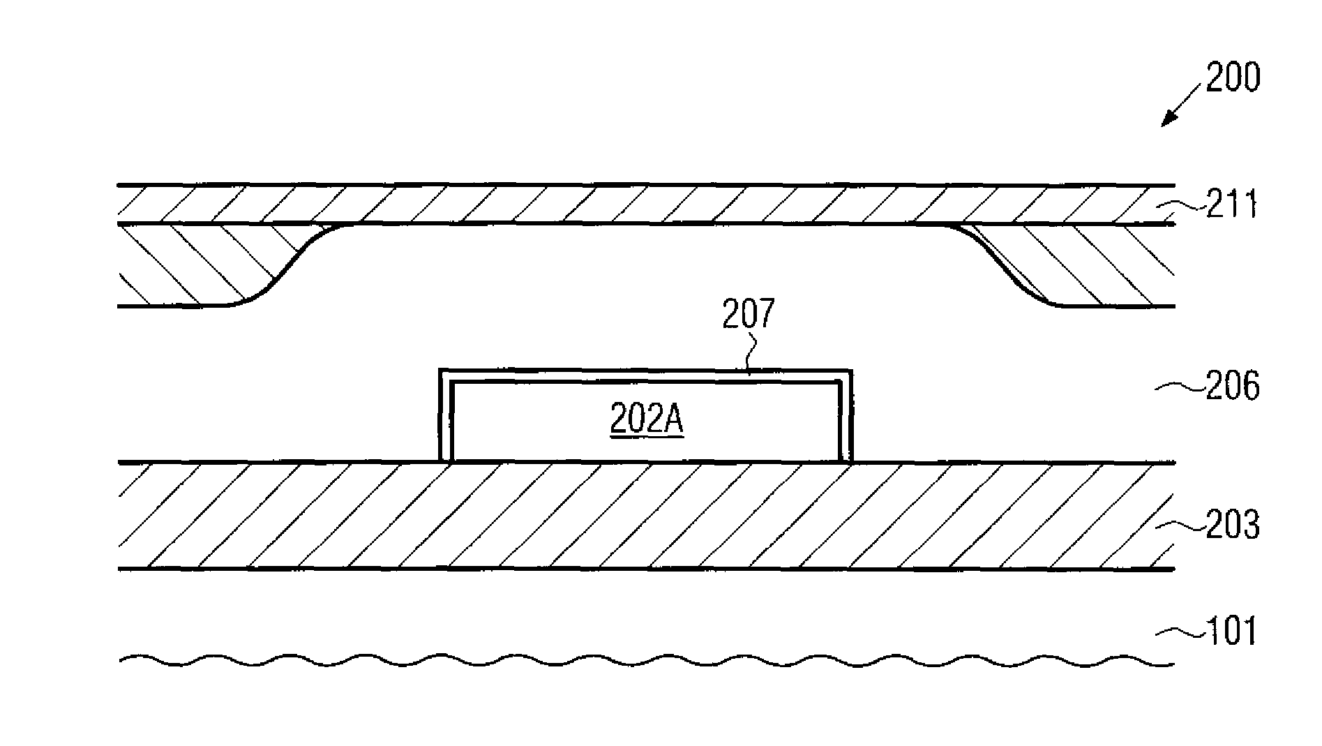
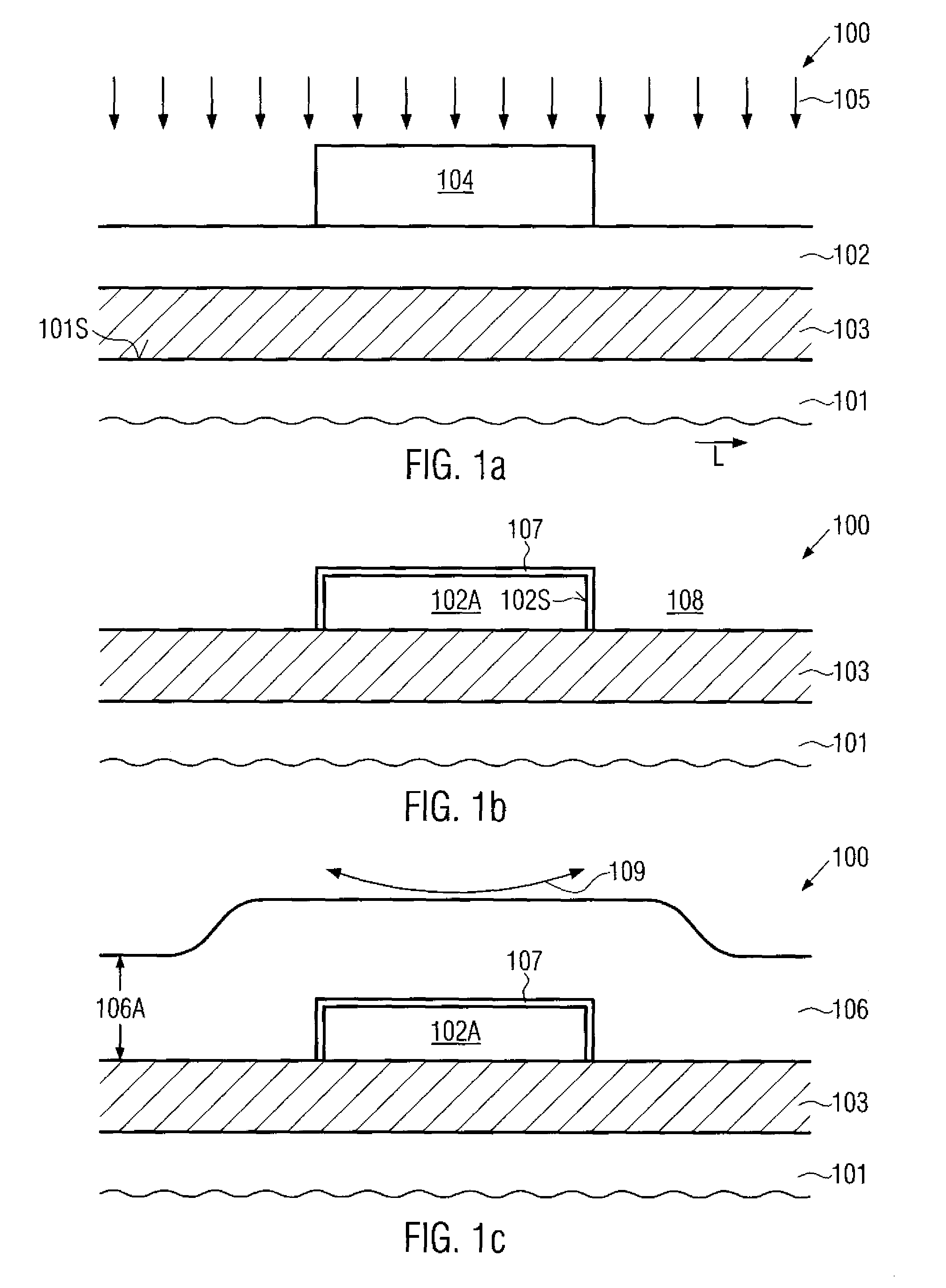
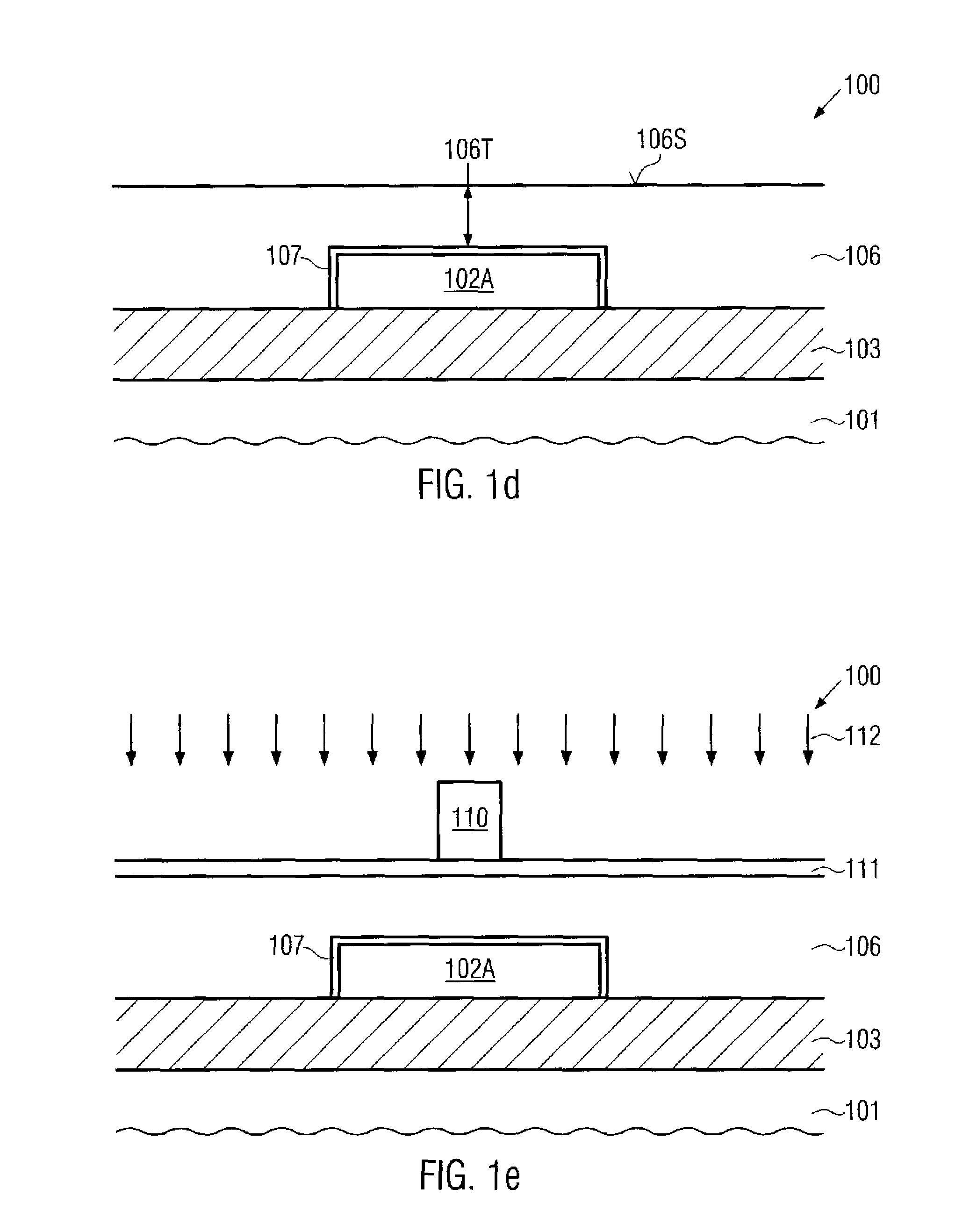
[0011]Generally, the subject matter disclosed herein is directed to a technique that enables the formation of semiconductor lines, such as gate electrodes, on the basis of an advanced lithography process with enhanced surface topography, while, at the same time, a device architecture including non-filled isolation trenches may be provided. For this purpose, the pronounced surface topography resulting from the deposition of a material layer above a structured semiconductor “island” may be efficiently planarized prior to performing further patterning steps for obtaining a conductive semiconductor line, such as a gate electrode, from the previously formed material layer. In other aspects, an isolation trench may be formed after the patterning of a gate electrode, thereby providing an enhanced surface topography for the patterning process of the gate electrode, while the isolation trench may also be formed on the basis of a planarized surface topography, thereby providing enhanced lithography conditions for the trench patterning process.

Problems solved by technology

Upon reducing the transistor dimension, the transistor width is typically also reduced in view of packing density and switching speed, which may, however, reduce the drive current capability.
While the resistivity of the metal lines may be improved by replacing the commonly used aluminum by, for example, copper and copper alloys, process engineers are confronted with a challenging task when an improvement in the electrical characteristics of silicon-containing semiconductor lines and semiconductor contact regions is required.
Although a plurality of advantages may be associated with the above-described approach, the precise patterning of the gate electrode may be significantly compromised by the corresponding pronounced surface topography of the device surface prior to and during the patterning process, in particular when highly scaled transistors are considered.
For highly sophisticated applications, however, any surface variations may have a negative influence, since, for instance, the depth of focus of modern lithography tools is typically reduced with a reduction of exposure wavelength.
Hence, the potential advantages provided by the above-described process flow for forming a mesa isolation may be partially or completely offset by process non-uniformities during the patterning of the gate electrodes, in particular for highly scaled devices, thereby rendering the conventional mesa isolation approach less attractive.

Method used


Image

  • Method of enhancing lithography capabilities during gate formation in semiconductors having a pronounced surface topography
  • Method of enhancing lithography capabilities during gate formation in semiconductors having a pronounced surface topography
  • Method of enhancing lithography capabilities during gate formation in semiconductors having a pronounced surface topography

Examples


Embodiment Construction

[0026]Various illustrative embodiments of the invention are described below. In the interest of clarity, not all features of an actual implementation are described in this specification. It will of course be appreciated that in the development of any such actual embodiment, numerous implementation-specific decisions must be made to achieve the developers' specific goals, such as compliance with system-related and business-related constraints, which will vary from one implementation to another. Moreover, it will be appreciated that such a development effort might be complex and time-consuming, but would nevertheless be a routine undertaking for those of ordinary skill in the art having the benefit of this disclosure.

[0027]The present subject matter will now be described with reference to the attached figures. Various structures, systems and devices are schematically depicted in the drawings for purposes of explanation only and so as to not obscure the present disclosure with details ...


PUM


Abstract

In a mesa isolation configuration for forming a transistor on a semiconductor island, an additional planarization step is performed to enhance the uniformity of the gate patterning process. In some illustrative embodiments, the gate electrode material may be planarized, for instance, on the basis of CMP, to compensate for the highly non-uniform surface topography, when the gate electrode material is formed above the non-filled isolation trenches. Consequently, significant advantages of the mesa isolation strategy may be combined with a high degree of scalability due to the enhancement of the critical gate patterning process.

Description

BACKGROUND OF THE INVENTION[0001]1. Field of the Invention[0002]Generally, the present disclosure relates to the field of fabrication of integrated circuits, and, more particularly, to semiconductor devices having conductive lines, such as gate electrodes of field effect transistors, which are formed on a pronounced surface topography.[0003]2. Description of the Related Art[0004]In modern ultra-high density integrated circuits, device features are steadily decreased to enhance device performance and functionality. One important circuit element in complex integrated circuits is a field effect transistor, which represents a component having a channel region, whose conductivity may be controlled by an electric field that is generated by applying a control voltage to a gate electrode formed near the channel region and separated therefrom by a gate insulation layer. The channel region is generally defined by respective PN junctions formed by an interface of highly doped drain and source ...

Claims


Application Information

Patent Timeline
Patent Type & Authority Patents(United States)
IPC IPC(8): H01L21/4763
CPCH01L21/28123H01L29/66772
Inventor GERHARDT, MARTINTRENTZSCH, MARTINFORSBERG, MARKUSHORSTMANN, MANFRED
Owner TAIWAN SEMICON MFG CO LTD
Learn More