Peak suppression control apparatus

a control apparatus and amplifier technology, applied in the field of transmission amplifiers, can solve the problems of reducing the cutoff signal, limiting the degradation of the reception characteristic, and degrading the spectrum characteristic in a large degree, and achieve the effect of reducing the papr of the signal and high efficiency

Inactive Publication Date: 2012-01-24
FUJITSU LTD
View PDF19 Cites 3 Cited by
  • Summary
  • Abstract
  • Description
  • Claims
  • Application Information

AI Technical Summary

Benefits of technology

[0027]The purpose of the present invention is to suppress a peak power of a transmission signal to be input to a transmission amplifier so that the transmission amplifier, while operating in high efficiency, is able to amplify and output the transmission signal satisfying the required quality.

Problems solved by technology

In the clip method, only a least necessary transmission signal S(t) is suppressed, reducing the cutoff signal and hence limiting a degradation of a reception characteristic.
On the other hand, generating a high frequency component because the edge of suppression is not smooth, hence resulting in degrading greatly the spectrum characteristic as shown in FIG. 6.
A degradation of a signal quality (i.e., reception quality and spectrum), however, needs to be allowed to some extent because a signal is cut off.
This in turn requires the transmission amplifier to suppress a transmission power if the same amplifier is to be used; or a bulky, expensive, and large-gain transmission amplifier if it is to be operated at a specified power.

Method used


Image

  • Peak suppression control apparatus
  • Peak suppression control apparatus
  • Peak suppression control apparatus

Examples


first embodiment

[0084]The present embodiment is configured to change a degree of peak suppression of a transmission signal by obtaining quality requirement information from a baseband signal generation unit.

[0085]FIG. 8 is a block diagram showing a configuration of the first embodiment of the present invention.

[0086]The first embodiment comprises a baseband signal generation unit (i.e., BB signal generation unit) 1, a peak suppression threshold value control unit 2 and a peak suppression unit 3. The baseband signal generation unit 1 converts a voice signal at the time of a telephone call (noted as “call” hereinafter) and various data into a baseband signal suitable to a radio transmission, and output their converted signal to the peak suppression unit 3. When outputting a baseband signal to the peak suppression unit 3, the baseband signal generation unit 1 outputs information (a modulation method and a coding ratio) related to the baseband signal to the peak suppression threshold value control unit...

second embodiment

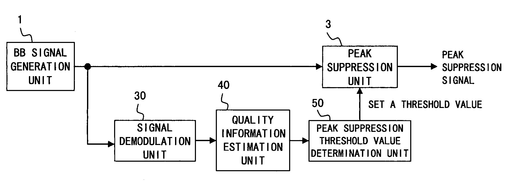
[0091]The first embodiment is configured to obtain the quality information of a signal from the baseband signal generation unit 1 as described above. The second estimates a signal quality based on a baseband signal generated by the baseband signal generation unit, and determines a degree of peak suppression based on the signal quality.

[0092]FIG. 10 is a block diagram showing a configuration of the second embodiment of the present invention. The same component sign is assigned to the same constituent component as that of the first embodiment of FIG. 8 in the showing of FIG. 10.

[0093]The second embodiment comprises a baseband signal generation unit 1, a peak suppression unit 3, a signal demodulation unit 30, a quality information estimation unit 40 and a peak suppression threshold value determination unit 50.

[0094]The signal demodulation unit 30 converts a baseband signal input from the baseband signal generation unit 1 into a signal allowing an extraction of the quality information (...

third embodiment

[0130]The third embodiment is configured to estimate a signal quality based on a baseband signal output from a baseband signal generation unit 1 and on a signal of a result of applying a peak suppression process to a baseband signal output from a peak suppression unit 3, and set a threshold value (i.e., a peak suppression threshold value) to be output to the peak suppression unit 3 based on the estimated signal quality. The signal quality uses, for example, BER (Bit Error Rate), EVM (Error Vector Magnitude) and “an attenuation of a signal power due to peak suppression” (abbreviated as “signal power attenuation” hereinafter).

[0131]Different from the case of quality information being directly known, such as a modulation method, when estimating a signal quality degraded by the peak suppression unit 3, it is necessary to estimate a signal quality by carrying out peak suppression once at the peak suppression unit 3 and repeat the process of setting a threshold value based on the estimati...


PUM


Abstract

A peak suppression threshold value control unit receives an input of quality requirement information, such as a modulation system and coding ratio, from a baseband signal generation unit, determines a threshold value of a peak suppression unit based on the quality requirement information and outputs the threshold value to a peak suppression unit. The peak suppression unit applies a peak suppression control to a baseband signal input from a baseband signal generation unit based on the threshold value and outputs a signal (i.e., a peak suppression signal) applied by the peak suppression process.

Description

BACKGROUND OF THE INVENTION[0001]1. Field of the Invention[0002]The present invention relates to a transmission amplifier and in particular to an apparatus controlling a degree of peak suppression at a peak suppression unit for suppressing a peak power of an input signal of the transmission amplifier.[0003]2. Description of the Related Art[0004]The next generation mobile communication is premised on an adoption of the Orthogonal Frequency Division Multiplexing (OFDM) and Multiple Input Multiple Output (MIMO). When adopting these, a power consumption of a radio frequency (RF) circuit must be reduced. The RF circuit is constituted by electronic components such as an antenna, power amplifier, RF filter, and AD converter. Among these electronic components, a reduction of power consumption of a power amplifier (named as “transmission amplifier” hereinafter) is especially important.[0005]A linear amplification is required of a transmission amplifier for use in a digital radio communicatio...

Claims


Application Information

Patent Timeline
Patent Type & Authority Patents(United States)
IPC IPC(8): H04L25/03H04K1/02H04L25/49
CPCH04B1/0475
Inventor HAMADA, HAJIMEKUBO, TOKURONAGATANI, KAZUOISHIKAWA, HIROYOSHIFUDABA, NOBUKAZU
Owner FUJITSU LTD
Why Eureka
Try Eureka