Multiport amplifiers in communications satellites

a multi-channel amplifier and satellite technology, applied in the field of multi-channel amplifiers, can solve the problems of lack of isolation between signals routed through the mpa and the flexibility with which they can distribute power over the coverage area

Active Publication Date: 2012-01-24
ASTRIUM GMBH
View PDF19 Cites 21 Cited by
  • Summary
  • Abstract
  • Description
  • Claims
  • Application Information

AI Technical Summary

Benefits of technology

[0011]It is a more specific object of the present invention to provide a multiport amplifier for operating at Ku / Ka bands wherein phase and gain parameters may be monitored and corrected, at least as often as necessary, so as to maintain aligned phase and gain relationships within the multiport amplifier.
[0017]Since feedback control loops are, in accordance with the invention, specifically provided, phase and gain adjustments may be carried out as often as desired, during the operation of the multiport amplifier within a satellite communication system—thus rendering the amplifier suitable for operation at the higher Ku and Ka bands.
[0018]The present invention proposes, in a preferred embodiment, a system of feedback loops embodied in the MPA to maintain phase and amplitude tracking. These loops may include power sensors located at specific “null points” in the MPA Output Network (ONET), at which the power level is zero for a signal at a given input port and if tracking is achieved. If the power level at these points is not zero, then the sensors produce outputs which are fedback to commandable phase shifters and gain adjusters in series with the individual amplifier units to achieve the required nulls and hence tracking performance.

Problems solved by technology

However, they are much restricted in the flexibility with which they can distribute this power over the coverage area.
However a concomitant problem with an MPA is that of cross-talk between MPA output ports, and in general a lack of isolation between signals routed through the MPA.
The problems of phase and amplitude misalignment of individual amplifiers of an MPA at the Ku / Ka-bands, and hence that of isolation and signal combining performance, become considerably greater and may bring the feasibility of operating MPAs at these frequencies onboard a satellite and over the required service life into question.

Method used


Image

  • Multiport amplifiers in communications satellites
  • Multiport amplifiers in communications satellites
  • Multiport amplifiers in communications satellites

Examples


Embodiment Construction

Nomenclature

A=Amplifier complex gain

C, Cnm=Hybrid transfer matrix, and transfer coefficient (input m to output n)

G=Amplifier real gain.

pm=Input signal voltage at input port m

qn=Output signal voltage at output port n

Φ, Φnm=Overall MPA transfer matrix, and matrix element (input m to output n)

Γ, Γnm=MPA INET transfer matrix, and matrix element (input m to output n)

Θ=Amplifier phase shift.

Ω, Ωnm=MPA ONET transfer matrix, and matrix element (input m to output n)

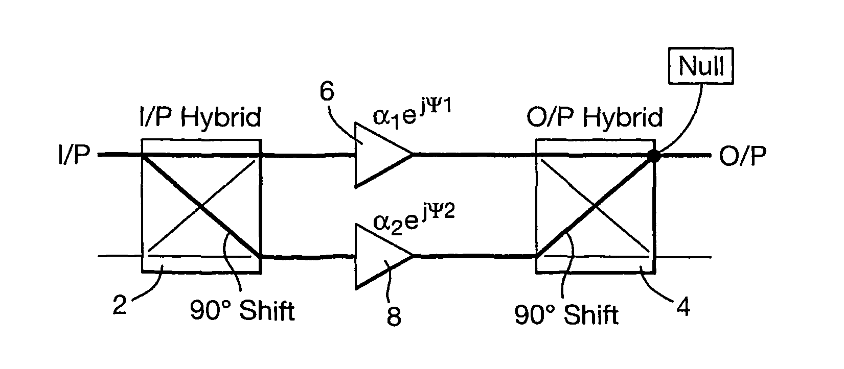
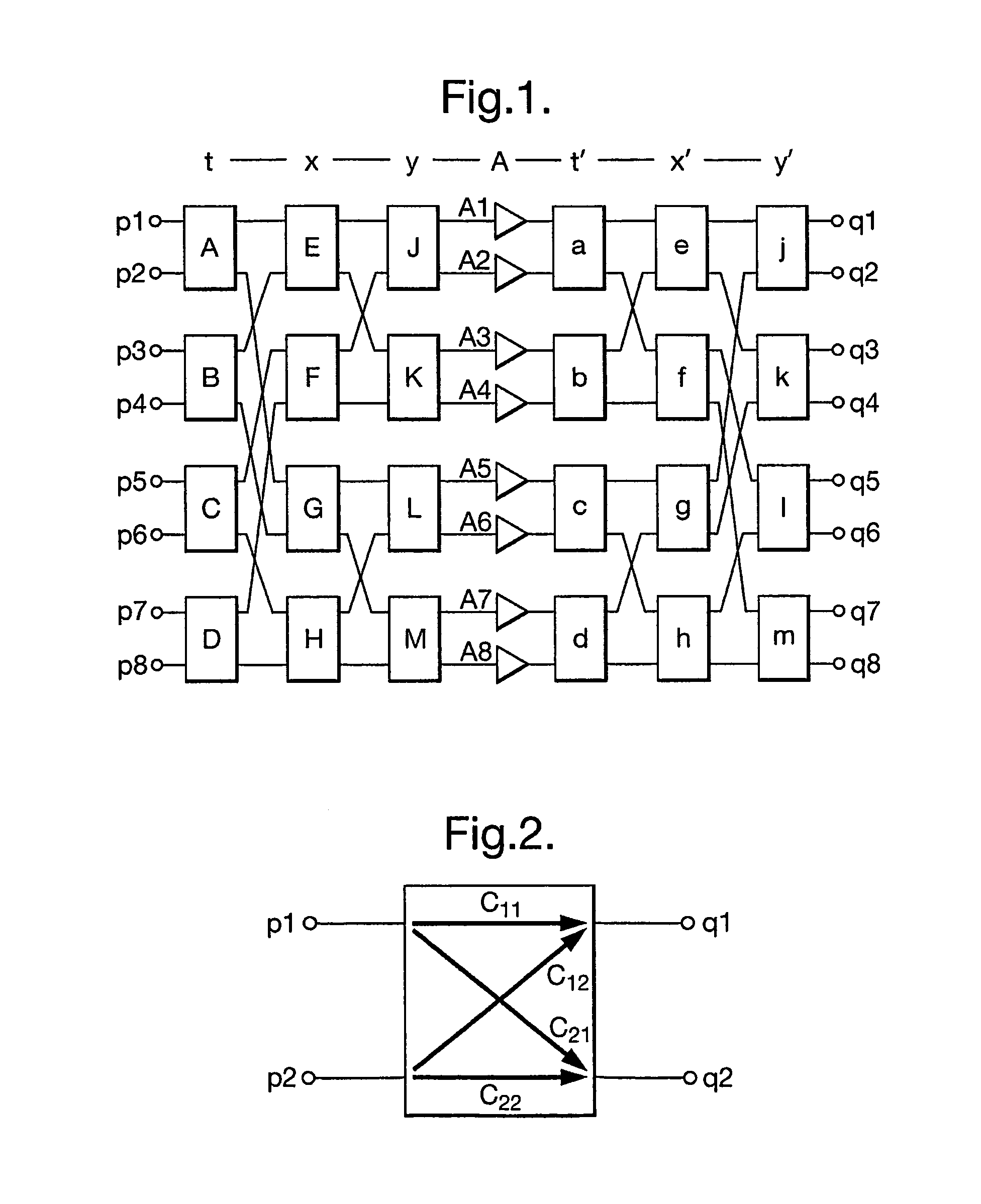
[0040]A diagram of an 8 port MPA is shown in FIG. 1. It comprises a set of 3 columns t, x, y of 4 input hybrids, a single column A of 8 amplifiers and a set of 3 columns t′, x′, y′, of 4 output hybrids. A circuit definition of an hybrid (input or output hybrid) is presented in FIG. 2. The input and output signals, p1 & p2 and q1 & q2, are assumed to be complex. The hybrid transfer function is represented thus:

[0041](q⁢⁢1q⁢⁢2)=(C11C12C21C22)⁢(p⁢⁢1p⁢⁢2)(1)

[0042]where C11, C12, C21, C22 are all invariable complex coefficients which c...


PUM


Abstract

Feedback loops are used within a Multiport Amplifier (MPA) of a communications satellite to maintain phase and amplitude tracking and hence isolation and combining performance. at Ku and Ka-bands, for which there is increasing interest in MPA applications, and where wavelengths are short and maintenance of phase / amplitude tracking becomes highly challenging. Feedback loops are located at strategic points within the MPA Output Network (ONET) to detect tracking errors and provide compensation. Errors are detected through power measurements at “null points”, with zero power corresponding to accurate tracking. The feedback loops adjust the MPA phase / gains such that the levels at these points are maintained at zero. The scheme operates with a pilot signal for measurement of nulls, injected at one of the MPA inputs.

Description

CROSS-REFERENCE TO RELATED APPLICATIONS[0001]This application is a national phase application of PCT / GB2008 / 001553 filed on May 2, 2008, which in turn claims priority from GB Application No. 0708718.2 and EP Application No. 07251874.9, both filed on May 4, 2007, each of which are incorporated by reference herein in their entirety.TECHNICAL FIELD[0002]This invention relates to multiport amplifiers for use within a satellite communication system, and specifically to a method and apparatus for maintaining isolation within multiport amplifiers.BACKGROUND ART[0003]Interest continues to grow in the application of Multiport Amplifiers (MPAs) to Ku and Ka-band satellite payloads—See for example, A Couchman, D. Jones, “Optimized Multiport Amplifiers for Wideband Multi-beam Satellites”, AIAA, 24th International Communications Satellite Systems Conference, San Diego, USA, June 2006; A. Anakabe, et al, “Ka-band Multi-port Amplifier Characteristics for Space Telecommunication Operation”, 6th Int...

Claims


Application Information

Patent Timeline
Patent Type & Authority Patents(United States)
IPC IPC(8): H04B7/185H04B7/00H04B1/00H01Q11/12
CPCH03F1/0205H03F1/3235H03F1/345H03F3/602H03F3/68H03F1/3247H03F1/3282H03F2200/105H03F2200/192H03F2200/204H03F2200/451H03F2201/3212H03F2201/3218
Inventor COUCHMAN, ALAN DAVIDJONES, DARYL RICHARD
Owner ASTRIUM GMBH
Why Eureka
Try Eureka