Decelerating stop device for a movable member, in particular a furniture door or drawer, fittable to a stop surface of the movable member

a technology of decelerating stop and movable parts, which is applied in the direction of wing accessories, manufacturing tools, shock absorbers, etc., can solve the problems of requiring a relatively complex internal construction, requiring a relatively large amount of work, and the action developed by the device in this case may not be sufficient to avoid slamming, etc., to achieve low manufacturing cost, high deceleration efficiency, and small dimensions

Inactive Publication Date: 2012-01-31
ITW IND COMPONENTS SRL
View PDF17 Cites 13 Cited by
  • Summary
  • Abstract
  • Description
  • Claims
  • Application Information

AI Technical Summary

Benefits of technology

[0006]It is the object of the present invention to avoid such drawbacks by providing a decelerating device adapted to intercept an end-of-stroke part of a closing path of a mobile member, such as a furniture drawer or a door, presenting at the same time high decelerating efficiently and small dimensions, and further presenting low manufacturing cost and high assembly ease.
[0010]Specifically, the stem is thoroughly and fluid-tightly mounted through the sealed chamber with its intermediate portion, which integrally and coaxially carries the piston, and the elastic means are preferably arranged mounted inside the sealed chamber, submerged in use in the viscous fluid, in order to attenuate to the maximum all operating noise.
[0011]In this manner, along with an extremely compact design, it is obtained the advantage of being able to maintain the volume of the sealed chamber unchanged in any position of the stem, simply by making the first and second ends of the stem of the same radial section; indeed, as the first end of the stem progressively penetrates in the sealed chamber in consequence of the motion of the stem towards the retracted position, the second end of the stem exits from the sealed chamber and, according to another aspect of the invention, is accommodated within a seat obtained in a closing cap of a casing delimiting the sealed chamber and defined by a tubular portion of the cap, which is overhangingly projected within the sealed chamber itself, thus reducing the axial dimensions of the device.
[0012]Preferably, the piston is provided with a mobile sealing member to choke the hydraulic communication between the two portions of the sealed chamber only during the stroke of the stem towards said retracted position. In this manner, it is possible to develop the maximum resistance to sliding of the stem only during the stroke towards the retracted position, while the stroke towards the extracted position is essentially only imperceptibly decelerated, thus ensuring prompt reaction times of the deceleration device according to the invention.

Problems solved by technology

The device according to EP1162338B1 is essentially based on the combined action of a spring and a viscous fluid which act on a piston integral with a stem integral with a pushrod which cooperates in use with the mobile member to be decelerated, which stem is fluid-tightly sliding in a body containing the spring and the viscous fluid; the known described device, while being satisfactory as a whole, presents the drawback of requiring a relatively complex internal construction in order to allow the free movement of the piston in the viscous oil bath, due to the volume reduction to which the space inside the body which contains the viscous fluid is subjected consequent to the progressive entrance of the stem in the same, during its sliding movement towards the retracted position.
More in general, the known device further presents a relatively high cost and dimensions, specifically if a high contrast force on the piston is required.
During the opening step of the door or drawer, the stem further requires a certain time in order to resume the extracted position which may not be sufficient if an immediate closing step occurs, whereby the contrast action developed by the device in this case may not be sufficient to avoid slamming.
Finally, the assembly of the known device is relatively complex and may leave air bubbles in the viscous fluid which in use may produce noise or ‘rough’ operation despite the presence of means (such as compressible sponges) which attenuate the effects thereof.

Method used


Image

  • Decelerating stop device for a movable member, in particular a furniture door or drawer, fittable to a stop surface of the movable member
  • Decelerating stop device for a movable member, in particular a furniture door or drawer, fittable to a stop surface of the movable member
  • Decelerating stop device for a movable member, in particular a furniture door or drawer, fittable to a stop surface of the movable member

Examples


Embodiment Construction

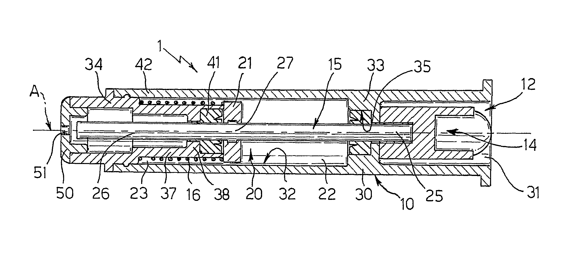
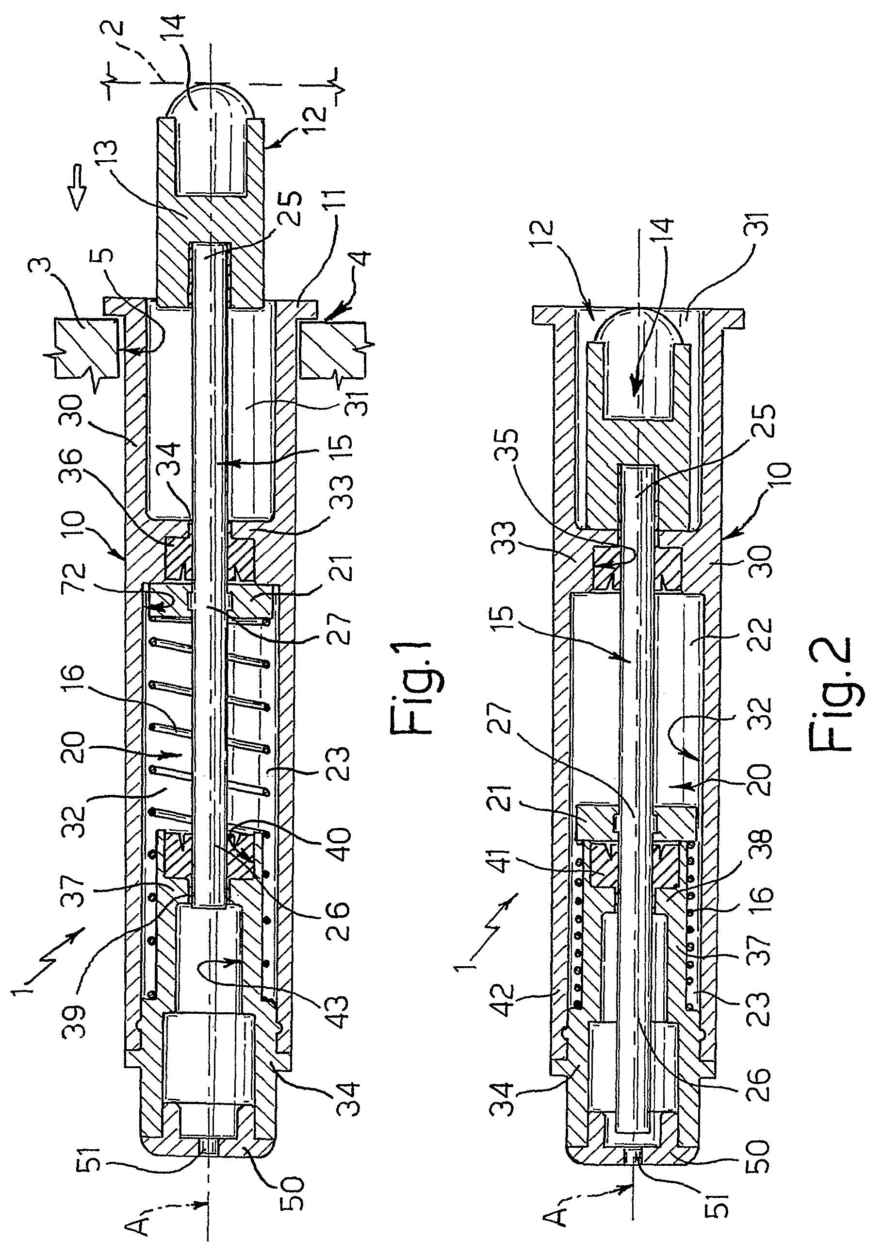
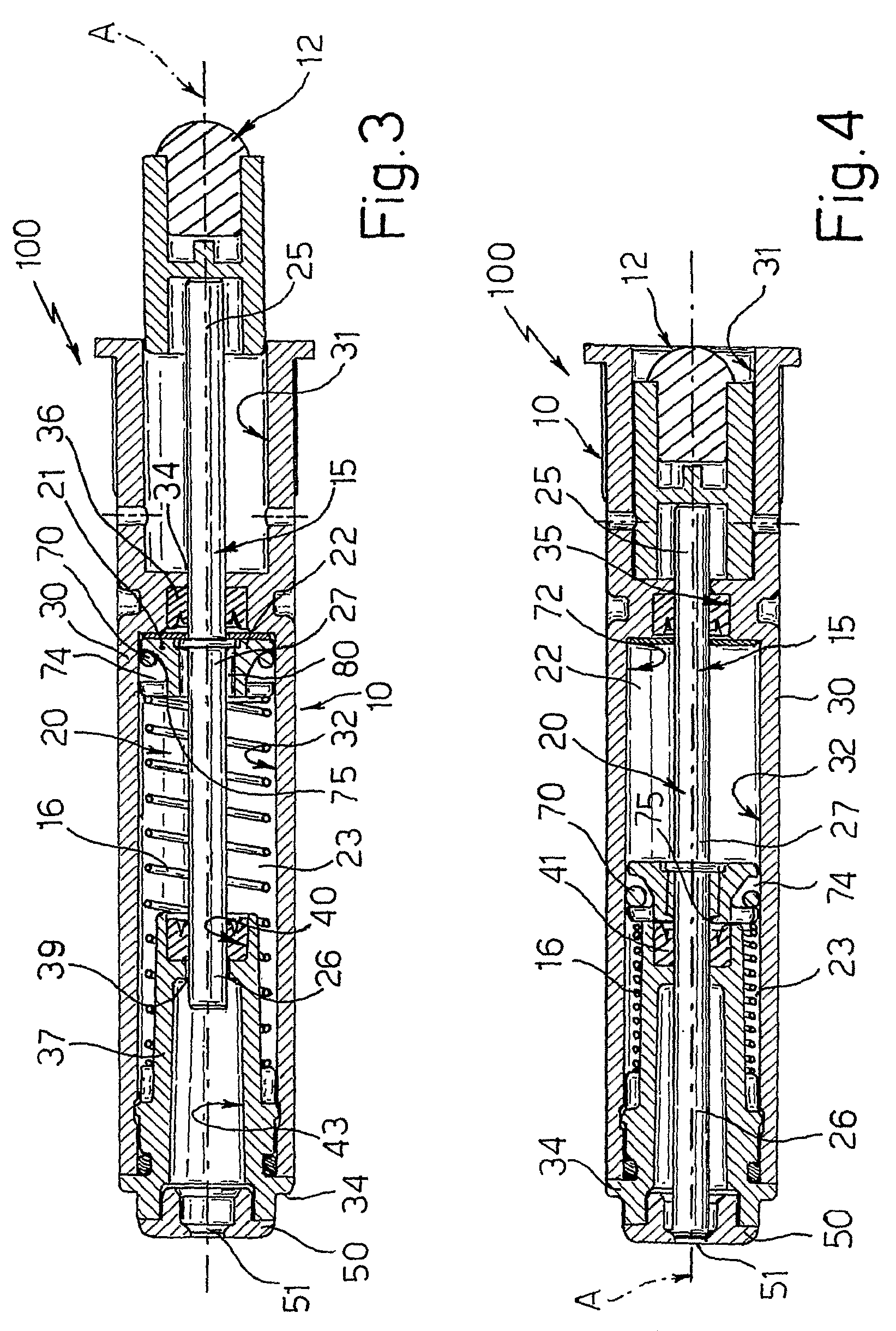
[0017]With reference to FIGS. 1 and 2, reference number 1 indicates as a whole a decelerating device of the type adapted to intercept an end-of-stroke part of a closing path (shown by the arrow in FIG. 1) of a mobile member 2, such as a drawer or a door, of a piece of furniture 3, of which only a part of an abutting or end-of-stroke surface 4 for mobile member 2 is shown for the sake of simplicity.

[0018]Device 1 comprises a body 10 fittable in use to surface 4, e.g. in a seat 5 of piece of furniture 3 and abutting against surface 4 with a collar 11, and a pushrod 12 at least in part overhanging from body 10 in at least one extracted position thereof from body 10, shown in FIG. 1, and being adapted to cooperate in use with mobile member 2; pushrod 12, which in turn comprises a bushing 13 and a feeler pad 14 carried by bushing 13, is integrally mounted on a stem 15 slidingly accommodated in body 10 against the bias of elastic means 16 between the mentioned extracted position of pushro...


PUM


Abstract

A decelerating device intended to intercept an end-of-stroke part of a closing path of a mobile member, such as a furniture drawer or door, including: a body fastenable in use to an abutting surface for the mobile member and internally defining a sealed chamber filled in use with a viscous fluid; a pushrod at least in part overhanging from the body and being adapted to cooperate in use with the mobile member, the pushrod being integral with a stem slidingly accommodated in the body against the bias of elastic means between an extracted position of the pushrod and a retracted position; and a piston accommodated in the sealed chamber so as to divide it into two portions hydraulically connected to each other and mechanically connected to the stem; wherein the stem presents a first end integrally connected to the pushrod and a second end opposite to the first, both slidingly accommodated in the body outside the sealed chamber and fluid-tightly towards the sealed chamber itself; the piston is provided with a mobile sealing member to choke the hydraulic communication between the two portions of the sealed chamber only during the stroke of the stem towards the retracted position.

Description

RELATED APPLICATIONS[0001]The present application is based on International Application Number PCT / IB2007 / 000817 filed Mar. 29, 2007, and claims priority from Italian Application Number TO2006A000242 filed Mar. 31, 2006, the disclosures of which are hereby incorporated by reference herein in their entirety.TECHNICAL FIELD[0002]The present invention relates to an end-of-stroke decelerating device for a mobile member, specifically a furniture door or drawer, applicable to an abutting surface for the mobile member in order to intercept an end-of-stroke part of a closing path of the mobile member itself.BACKGROUND ART[0003]It is known from EP1162338B1 to apply decelerating devices, also referred to as shock absorbers, to single or modular pieces of furniture in order to prevent the mobile furniture member, e.g. a door or a drawer, from violently slamming onto an abutting surface or end-of-stroke for the same, during the closing phase of the door or drawer, e.g. following the reception o...

Claims


Application Information

Patent Timeline
Patent Type & Authority Patents(United States)
IPC IPC(8): E05F3/00
CPCE05F5/08E05F5/10F16F9/20F16F9/3242E05Y2201/21E05Y2201/212E05Y2201/256Y10T16/62E05Y2900/20Y10T16/61E05Y2201/264F16F9/32
Inventor BASSI, ALBERTO
Owner ITW IND COMPONENTS SRL
Why Eureka
Try Eureka