Power tong

a power tong and power technology, applied in the field of power tongs, to achieve the effect of high torque and high speed

Active Publication Date: 2012-02-07
WARRIOR RIG TECH LTD
View PDF12 Cites 24 Cited by
  • Summary
  • Abstract
  • Description
  • Claims
  • Application Information

AI Technical Summary

Benefits of technology

[0013]The present invention includes a main drive, rotary jaw and back-up jaw. The rotary jaw is supported and held in position by the use of opposed helical pinions / gears which support the rotary jaw vertically and guide bushings which locate it laterally. The rotary jaw hydraulic gripper cylinders are held in position by links and guide bushings that can withstand the torque parameters of the tong. Gripper cylinders can be moved in a range of travel by an eccentric. This provides for a tong that can accommodate a large range of pipe diameters (3.5 inch drillpipe to 9⅝ inch casing or larger). This large range can be accomplished without changing gripping jaws or jaw holders. A centralizing linkage ensures that the pipe is gripped concentrically with the tong axis of rotation. The tong does not require a mechanical device to close the radial opening. The on-board power source and rotary control system allow the present invention to have fully independently activated and controlled rotary hydraulic gripping of the tubular. It is capable of high torque for making and breaking and high speed for spinning, all within one mechanism. The present invention also overcomes the limitation of the spinning wrench engaging the stem area of the drillpipe which over time will cause fatigue in the stem area as the spinning and torquing according to the present invention is accomplished with the same jaw that engages the pipe on the tool joint. The open throat of the jaws according to the present invention allows the power tong to be selectively positioned around the pipe at the operators' discretion.

Problems solved by technology

Hydraulic and electrical power necessary for actuating the grippers is generated on board the rotating jaw since the continuous rotation does not allow for either hydraulic or electrical external connections.

Method used


Image

  • Power tong
  • Power tong
  • Power tong

Examples


Embodiment Construction

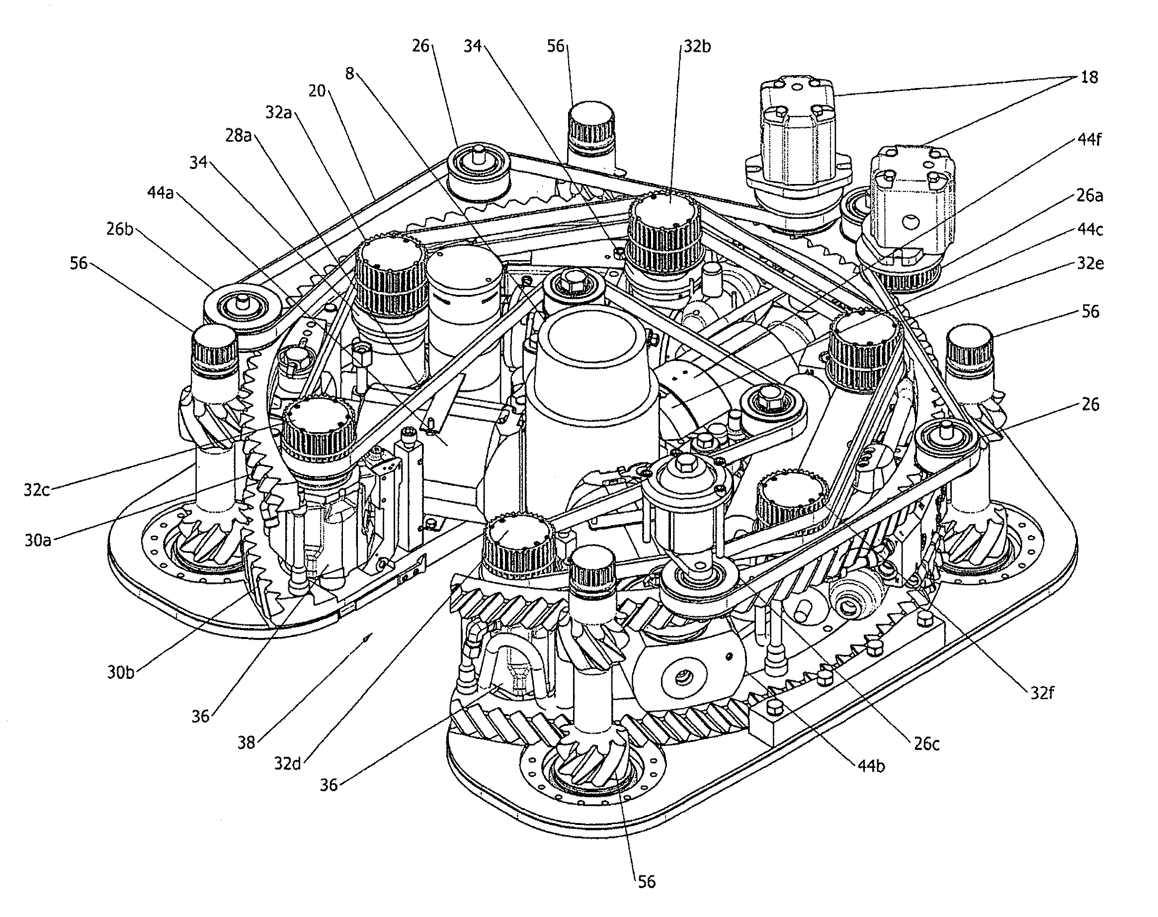
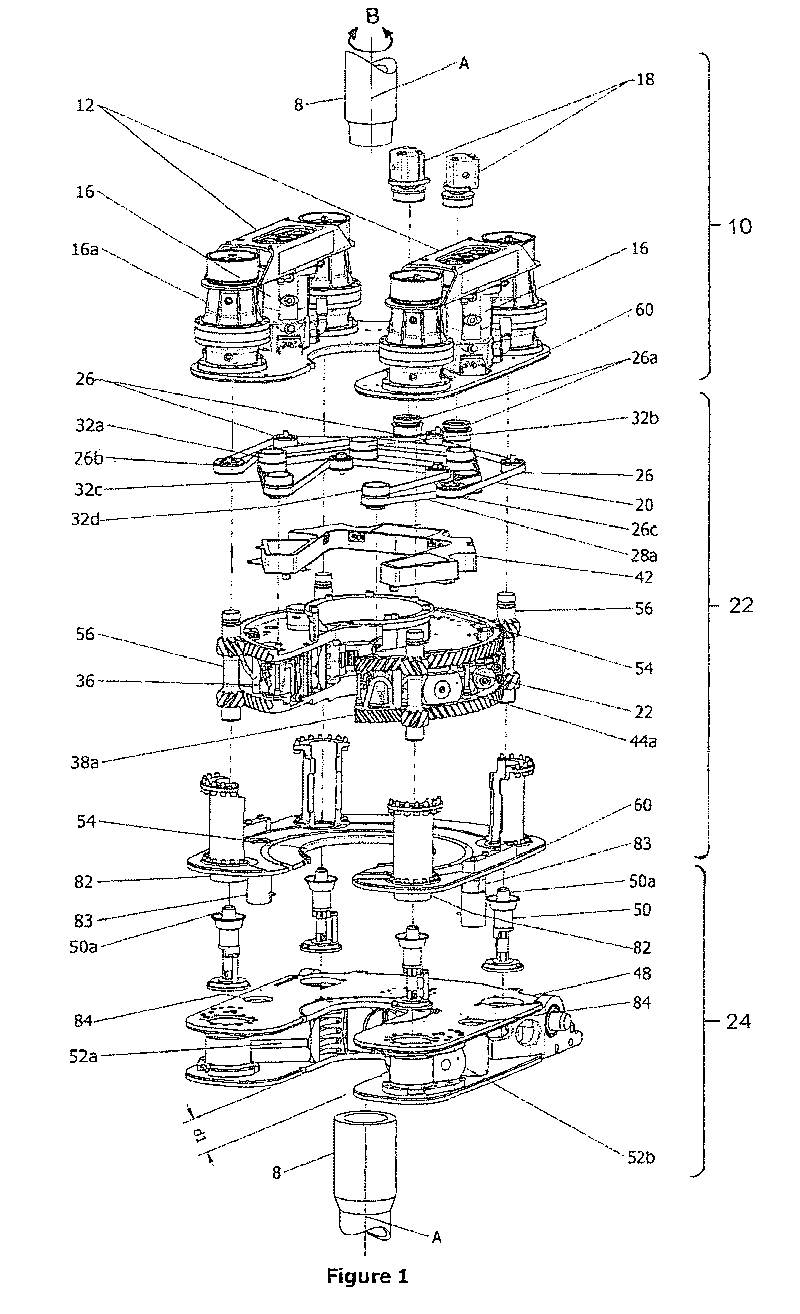
[0035]As seen in FIGS. 1 and 2, the power tong 6 according to the present invention may be characterized in one aspect as including three main sections mounted on a common axis A; namely a main drive section, a rotary jaw, and back-up jaw. Each of the sections contains actuators, as better described below. The main drive section 10 is located about the rotary jaw 22 and the backup jaw 48. The rotary jaw rotates relative to the main drive and back-up jaw. Both the rotary jaw and backup jaw clamp their respective sections of pipe. The rotary jaw is rotated by the main drive section independently of the other two sections in the sense that the rotary jaw is self-contained, having on-board hydraulic and electric power generators to power on-board radial clamps or grippers (collectively herein referred to as grippers), and an on-board serpentine secondary power transmission all configured to allow the insertion and removal of a pipe through a jaw opening from or into the center of the ja...


PUM


Abstract

A power tong continuously rotates tubulars for spinning and torquing threaded connections. Continuous rotation is achieved through a rotating jaw having grippers that grip the tubular and continuously rotate with it. Hydraulic and electrical power necessary for actuating the grippers is generated on board. A serpentine belt system turns the motors of the on-board hydraulic power unit and electric generators to supply the grippers with hydraulic and electrical power. The serpentine belt system is driven by a secondary drive mounted on a fixed frame. The rotating jaw is rotatably mounted to the fixed frame and driven during continuous three hundred and sixty degrees of rotation by a primary drive, mounted on the fixed frame. A fixed jaw is also mounted to the frame. Tubular grippers on the fixed jaw grip a first side of a tubular joint. The grippers on the rotating jaw grip the opposite second side of the tubular joint. High torque low-rotational speed applied to the rotating jaw torques the joint. Low torque high-rotational speed applied to the rotating jaw spins the joint.

Description

CROSS REFERENCE TO RELATED APPLICATION[0001]This application claims priority from U.S. Provisional Patent Application No. 61 / 064,032 filed Feb. 12, 2008 entitled Power Tong, and U.S. Provisional Patent Application No. 61 / 071,170 filed Apr. 16, 2008 entitled Power Tong.FIELD OF THE INVENTION[0002]This invention relates to the field of devices for rotating tubular members so as to make up or break out threaded joints between tubulars including casing, drill pipe, drill collars and tubing (herein referred to collectively as pipe or tubulars), and in particular to a power tong for the improved handling and efficient automation of such activity.BACKGROUND OF THE INVENTION[0003]In applicant's experience, on conventional rotary rigs, helpers, otherwise known as roughnecks, handle the lower end of the pipe when they are tripping it in or out of the hole. They also use large wrenches commonly referred to as tongs to screw or unscrew, that is make up or break out pipe. Applicant is aware that...

Claims


Application Information

Patent Timeline
Patent Type & Authority Patents(United States)
IPC IPC(8): B25B13/50E21B19/16
CPCE21B19/164
Inventor RICHARDSON, ALLAN STEWART
Owner WARRIOR RIG TECH LTD
Why Eureka
Try Eureka