Supercharge Your Innovation With Domain-Expert AI Agents!

Imaging system using enhanced spherical aberration and specifically sized FIR filters

a technology of spherical aberration and imaging system, applied in the field of imaging system, can solve the problems of affecting the design of electro-optic imaging system, affecting the overall system, and ignoring the synergies between optics and digital image processing subsystems,

Inactive Publication Date: 2012-02-07
RICOH KK
View PDF7 Cites 2 Cited by
  • Summary
  • Abstract
  • Description
  • Claims
  • Application Information

AI Technical Summary

Benefits of technology

The present invention provides a new type of imaging system that overcomes the limitations of previous designs. This system uses three parameters to relate the imaging optics, sensor array, and image processing: W0, U, and N. W0 is the amount of third order spherical aberration, U is the ratio of the sensor array's Nyquist frequency to the imaging optics' diffraction-limited frequency, and N is the number of rows in the image processing. By satisfying a specific equation, N can be determined based on W0 and U. The invention also includes methods for using these systems. This new design allows for improved image quality and reduced costs.

Problems solved by technology

In general, the familiarity required to master each of these domains hinders a unified perspective to designing electro-optic imaging systems.
One drawback to the traditional design approach is that synergies between the optics and the digital image processing subsystem may be overlooked.
The concatenation of two independently designed “best” subsystems may not yield the “best” overall system.
There may be unwanted interactions between the two independently designed subsystems and potential synergies between the two subsystems may go unrealized.
However, this is a design problem with a very large degree of freedom.
In the traditional approach, the separate design of the optics alone is a difficult problem with a large possible design space and it takes professional optical designers many years to master the task of selecting good designs within this design space.
Similarly, the subsequent design of the image processing is also a large possible design space and it also takes professionals in that field many years to master their art.
In the combined approach, the optics and image processing are designed together, thus the total possible design space includes both the optics design space and the image processing design space, thus compounding the complexity of the design problem.
In addition, many of the above approaches require the use of expensive optical elements (e.g., the introduction of additional phase plates, pupil masks, or other elements or the use of aspheres or other more complex optics) and / or complicated image processing (e.g., iterative deconvolution or ideal Wiener filters).

Method used


Image

  • Imaging system using enhanced spherical aberration and specifically sized FIR filters
  • Imaging system using enhanced spherical aberration and specifically sized FIR filters
  • Imaging system using enhanced spherical aberration and specifically sized FIR filters

Examples


Embodiment Construction

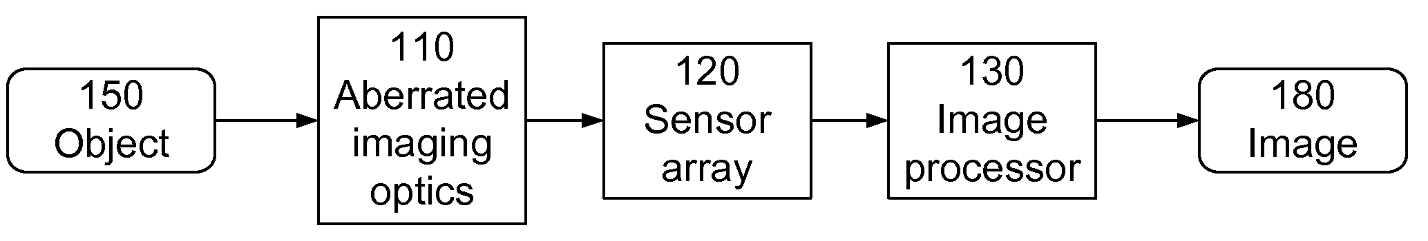
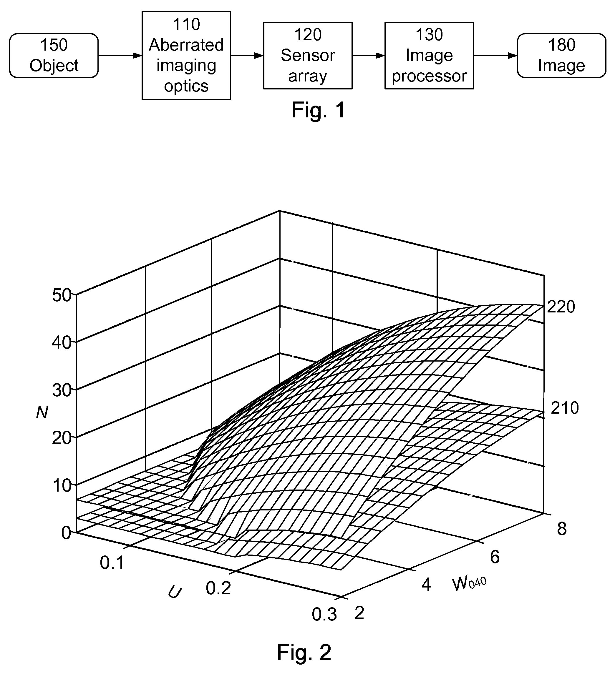
[0023]FIG. 1 is a block diagram of a digital-optical imaging system according to the invention. The imaging system includes imaging optics 110 (e.g., a lens assembly), sensor array 120 (e.g., CCD detector array) and image processor 130 (e.g., typically implemented in dedicated chips or software). The imaging system produces a digital image 180 of an object 150. It is a “digital-optical” imaging system in the sense that optics 110 are used to produce an image on the sensor array 120, and the captured image is digitally processed by the image processor 130.

[0024]Various aspects of the invention are especially beneficial for imaging systems used in consumer devices, for example a cell phone camera or digital camera. Many of these consumer applications operate primarily (or even exclusively) in the visible wavelength region, at F / #'s between approximately F / 2 and F / 6, and over fields of view up to about 60 degrees full field. The corresponding sensor arrays 120 often have pixel pitches ...


PUM


Abstract

A class of imaging systems in which the imaging optics, the sensor array and the image processing are related by three parameters: W040 the amount of third order spherical aberration, U the undersampling factor defined as the ratio of the Nyquist frequency of the sensor array divided by the diffraction-limited frequency of the imaging optics, and N the number of rows in the FIR implementation of the image processing. In one aspect, W040 is between approximately 2 and 8 waves, U is between approximately 0.05 and 0.30, and N satisfies an equation that defines the acceptable range of N as a function solely of W040 and U.

Description

BACKGROUND OF THE INVENTION[0001]1. Field of the Invention[0002]This invention relates to imaging systems in which specifically aberrated optics are balanced by specific digital image processing.[0003]2. Description of the Related Art[0004]Electro-optic imaging systems typically include imaging optics (e.g., a lens or mirror assembly), an electronic sensor array (e.g., CCD detector array) and a digital image processor (e.g., typically implemented in dedicated chips or software). Traditional methods for designing these systems generally involve fairly independent steps. The optics typically is designed with the goal of forming a high quality intermediate optical image at the sensor array. The sensor array often is dictated by the intended application, including resolution and cost factors. The digital image processing typically is designed after the optics, with the goal of compensating for remaining defects in the sampled intermediate optical image.[0005]The design stages typically ...

Claims


Application Information

Patent Timeline
Patent Type & Authority Patents(United States)
IPC IPC(8): H04N5/225H04N25/00
CPCG02B27/0025H04N5/2254H04N5/3572H04N25/615H04N25/61
Inventor FENG, GUOTONGROBINSON, M. DIRK
Owner RICOH KK
Features
  • R&D
  • Intellectual Property
  • Life Sciences
  • Materials
  • Tech Scout
  • Unparalleled Data Quality
  • Higher Quality Content
  • 60% Fewer Hallucinations
Learn More