
Radio transmitting apparatus and radio transmitting method

a radio transmission and apparatus technology, applied in the direction of wireless communication, sustainable building, wireless communication, etc., can solve the problems of delay twice as much delay of frame timing at the communication terminal delay of the arrival time of the rach by the length of propagation delay, so as to reduce the increase of the guard time in the random access area

Active Publication Date: 2012-02-07
PANASONIC INTELLECTUAL PROPERTY CORP OF AMERICA
View PDF9 Cites 17 Cited by
  • Summary
  • Abstract
  • Description
  • Claims
  • Application Information

AI Technical Summary

Benefits of technology

The present invention relates to a radio transmitting apparatus and a radio transmission method that can reduce guard time increase in random access areas and keep uplink data transmission areas. The technical effect of the invention is to estimate the propagation distance from a communicating party station based on a signal transmitted from the communicating party station and select a random access channel format of a frame length supporting the estimated propagation distance, from a plurality of random access channel formats of frame lengths supporting the propagation distances, to reduce guard time increase in the random access areas and keep uplink data transmission areas.

Problems solved by technology

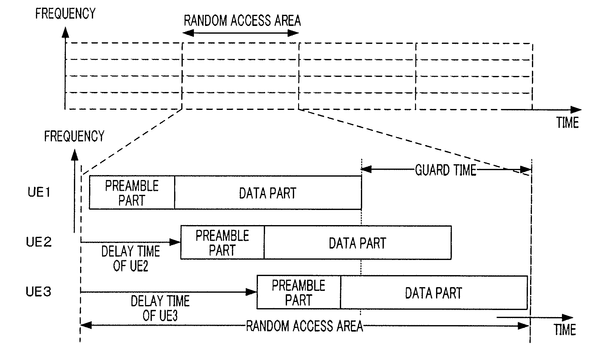
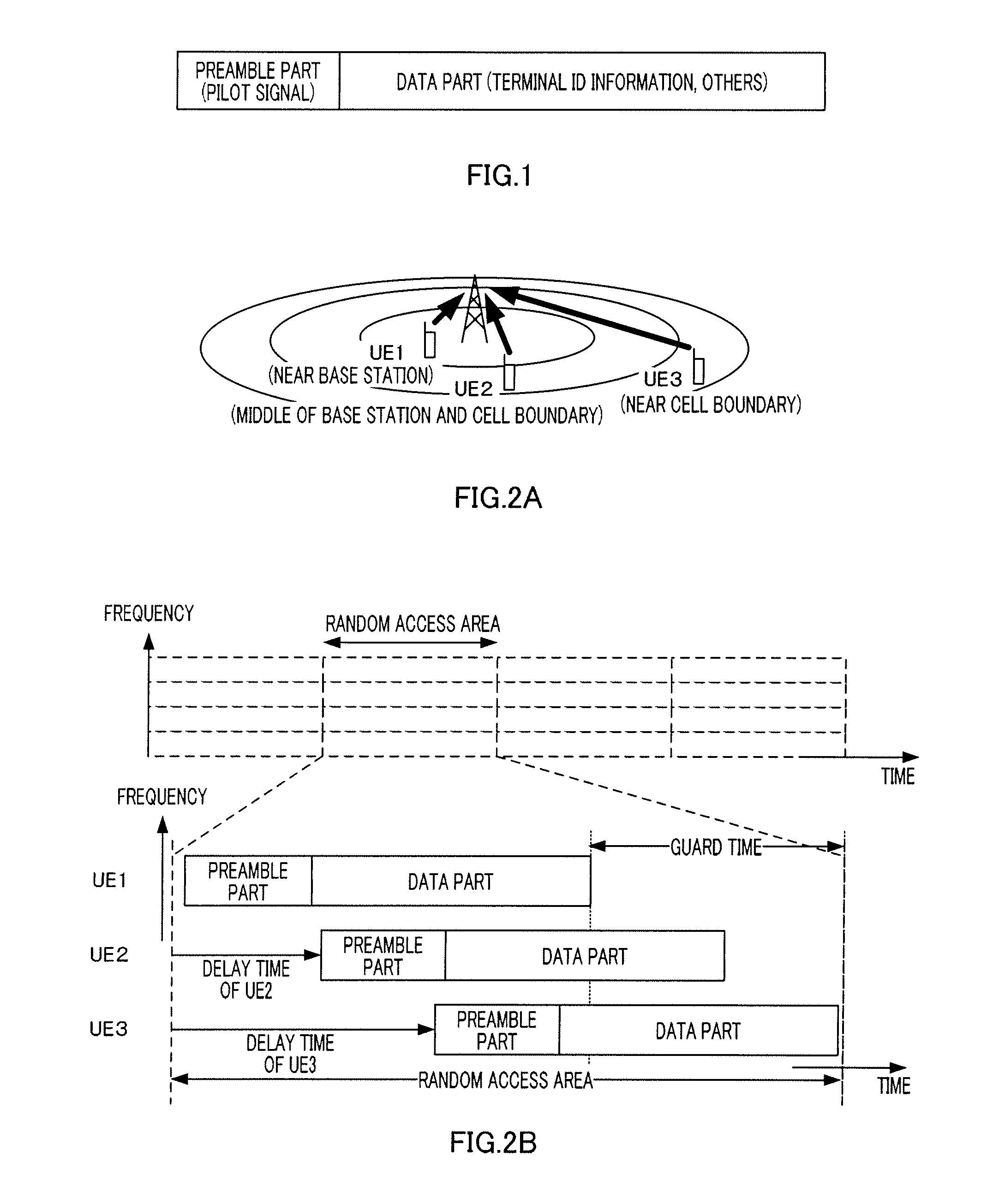
That is to say, if the time a downlink frame synchronization signal arrives at a communication terminal is delayed due to propagation delay, the frame timing at the communication terminal is also delayed by the length of the propagation delay.
Moreover, this communication terminal starts transmitting the RACH based on its own frame timing, and, consequently, the arrival of the RACH is further delayed by the length of propagation delay.
As a result, the arrival time for the RACH is delayed twice as much as a case without propagation delays.

Method used


Image

  • Radio transmitting apparatus and radio transmitting method
  • Radio transmitting apparatus and radio transmitting method
  • Radio transmitting apparatus and radio transmitting method

Examples


embodiment 1

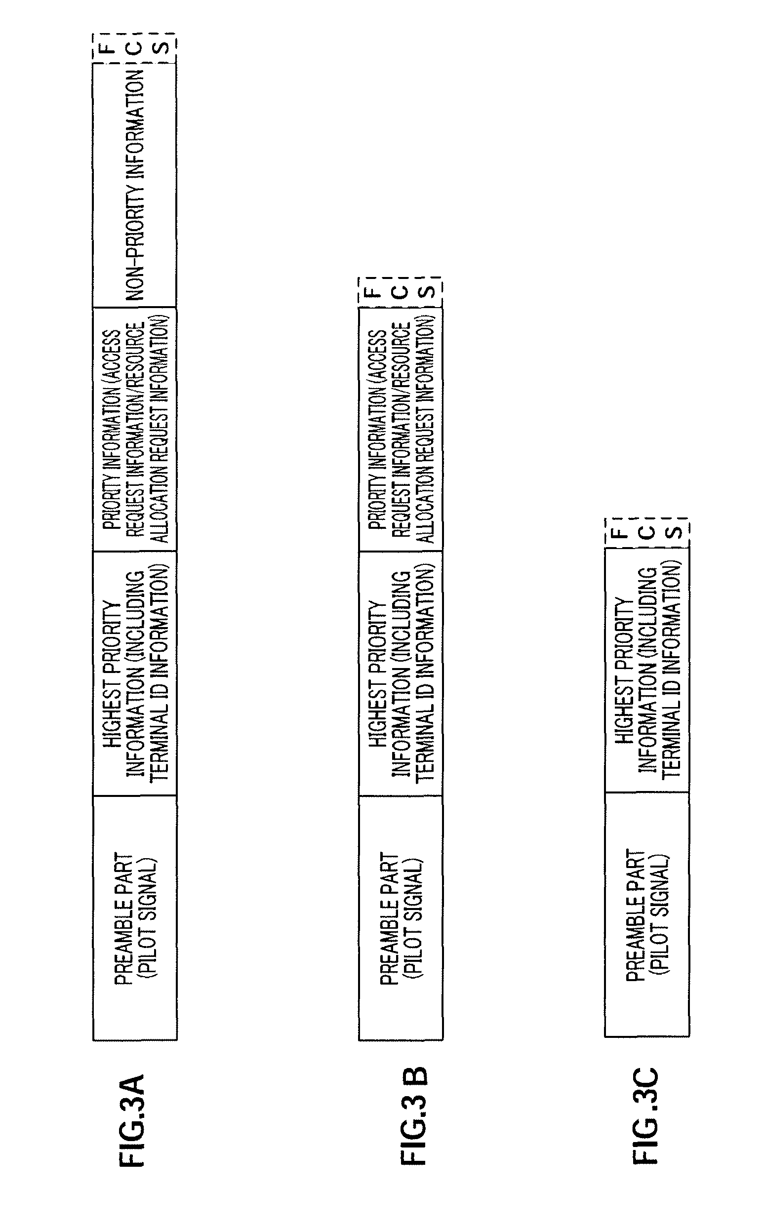
[0040]With Embodiment 1 of the present invention, three RACH formats of different lengths are prepared in advance. That is, the first RACH format of the longest frame length, a second RACH format of the second longest frame length, and a third RACH format of the shortest frame length are prepared.

[0041]On the other hand, the information transmitted in the RACH frames is classified into three levels of priority (i.e. significance), and the information that has to be transmitted in all RACH frames is the highest priority information of the highest priority. Moreover, the information that is produced when a RACH frame is generated, that is efficient to be transmitted in RACH frames (but can be transmitted in frames other than RACH frames), is priority information of the second highest priority. Moreover, the information, which can be transmitted in scheduled channels but is efficient to be transmitted in RACH is non-priority information of the lowest priority.

[0042]Here, specific examp...

embodiment 2

[0065]FIG. 8 is a block diagram showing the configuration of communication terminal 500 according to Embodiment 2 of the present invention. FIG. 8 is different from FIG. 4 in that FCS adding section 208 and coding section 209 are changed to FCS coding sections 501-1 to 501-4 and coding sections 502-1 to 502-4.

[0066]FCS adding section 501-1 adds an FCS to the information bits of the terminal identifier, and, coding section 502-1 performs error correction coding processing of the terminal identifier with a FCS, and outputs an encoded bit sequence of the terminal identifier to RACH data part arranging section 207.

[0067]FCS adding sections 501-2 to 501-4 and coding sections 502-2 to 502-4, similar to FCS adding section 501-1 and coding section 502-1, respectively process the access request information, resource allocation request information and non-priority information.

[0068]Based on the RACH format reported from RACH format selecting section 206, RACH data part arranging section 207 a...

embodiment 3

[0074]FIG. 11 is a block diagram showing the configuration of communication terminal 800 according to Embodiment 3 of the present invention. FIG. 11 is different from FIG. 8 in that additional information type storing section 801 is added, and RACH data part arranging section 207 is changed to RACH data part arranging section 802.

[0075]Additional information type storing section 801 stores the types of information arranged next to the highest priority information in the RACH formats and indicators showing these types (additional information indicators). Their corresponding relationships are shown in FIG. 12, for example, and, when the additional information type is “no additional information (in the third RACH format),” the additional information indicator is “000.” Moreover, similarly, the access request information is “001,” the resource allocation request information is “010,” the access request information and non-priority information is “011,” the resource allocation request in...


PUM


Abstract

A radio transmitting apparatus and a radio transmitting method wherein the increase of the guard time in a random access region is reduced to secure the data transmitting region of an upstream line. In this apparatus, when a received signal power estimated by a received signal power estimating part (205) is the higher, a RACH format selecting part (206) selects a RACH format having the longer frame length. Contrarily, when a received signal power estimated by the received signal power estimating part (205) is the lower, the RACH format selecting part (206) selects a RACH format having the shorter frame length. A RACH data part arranging part (207) appropriately selects, in accordance with the selected RACH format, top-priority information, such as terminal identifiers, priority information, such as connection request information or band assignment request information, and non-priority information and arranges RACH data parts.

Description

TECHNICAL FIELD[0001]The present invention relates to a radio transmitting apparatus and a radio transmission method.BACKGROUND ART[0002]Random access areas are provided in mobile communication systems represented by cellular communication systems and wireless LAN (Local Area Network) systems. A random access area refers to an uplink transmission area that is provided as when a communication terminal requests an initial access to a base station (or an access point) or when a new resource allocation request is issued in a centralized management system where a base station allocates transmission time and transmission band to communication terminals.[0003]The transmission timing for a random access channel (RACH) transmitting in a random access area is normally determined based on the synchronization timing in downlink. That is, a communication terminal establishes downlink frame timing synchronization using, for example, a frame synchronization pilot signal transmitted from a base sta...

Claims


Application Information

Patent Timeline
Patent Type & Authority Patents(United States)
IPC IPC(8): H04B7/005
CPCH04W74/002H04W74/0891Y02B60/50
Inventor IMAMURA, DAICHIMATSUMOTO, ATSUSHIIWAI, TAKASHIFUTAGI, SADAKITAKATA, TOMOFUMI
Owner PANASONIC INTELLECTUAL PROPERTY CORP OF AMERICA
Learn More