Graded resolution field of view CT scanner

a ct scanner and resolution technology, applied in the field of computerized tomography xray imaging and tomography scanners, can solve the problems of large detector arrays, large detector arrays, and general incomplete attenuation data, and achieves simple and relatively inexpensive production and satisfactory image quality

Active Publication Date: 2012-02-07
ARINETA
View PDF15 Cites 4 Cited by
  • Summary
  • Abstract
  • Description
  • Claims
  • Application Information

AI Technical Summary

Benefits of technology

[0012]An aspect of some embodiments of the present invention relates to providing a CT scanner having a FOV sufficient to encompass the width of a patient's body that is simpler and relatively inexpensive to produce in comparison with prior art CT scanners, yet provides CT images having image quality satisfactory for medical applications.
[0020]In accordance with an aspect of some embodiments of the invention, the X-ray source of the CT scanner is collimated so that X-rays from the source illuminate substantially only those regions of the detector array that are sensitive to X-rays. The collimating shielding results in a substantial decrease in exposure of a patient to X-rays during a CT-scan.
[0021]In some embodiment of the invention, shielding is used to decreases intensity of X-rays from the X-ray source that illuminate the at least one low resolution region of the detector array. For example, for a detector array having a high resolution region flanked by two low resolution wings, a “butterfly filter” having a smoothly varying thickness that increases with azimuth angle may be used to attenuate X-rays that illuminate the wings. Optionally, uniform thickness “plate filters” may be used to attenuate X-rays that illuminate the wings.
[0022]As a result of the configuration of detectors in an X-ray detector array in accordance with an embodiment of the invention, a number of detectors in the array is substantially reduced in comparison to prior art CT scanners having a same FOV. A CT scanner in accordance with an embodiment of the invention therefore requires less intricate and complicated mechanical and electronic support structures and may be produced relatively inexpensively. It is expected that CT scanners in accordance with embodiments of the invention will be affordable by a larger number of medical centers than the number of medical centers that can afford prior art CT scanners. It is also expected that individual medical centers will be able to afford a greater number of CT scanners in accordance with an embodiment of the invention than a number of prior art CT scanners that they can afford. CT scanners in accordance with an embodiment of the present invention are therefore expected to make the benefits of CT scanning available to an increased population of patients. In addition, the benefits will be able to be provided at a lower dose of radiation exposure to patients.
[0023]There is therefore provided in accordance with an embodiment of the invention, A CT scanner comprising: a rotor rotatable about an axis of rotation; an X-ray source mounted to the rotor having a focal spot from which an X-ray beam emanates; an X-ray detector array comprising a plurality of X-ray detectors for detecting X-rays in the X-ray beam; wherein the detector array has at least one high resolution region in which detectors have a high packing density and at least one low resolution region in which detectors have a low packing density and are separated by X-ray insensitive regions substantially larger than insensitive regions resulting from septa between detectors that function to reduce detector cross talk.

Problems solved by technology

If portions of an imaging region of a patient cannot fit inside the FOV for all view angles, attenuation data is generally incomplete and artifacts may be generated in images reconstructed from the data.
As a result, detector arrays of conventional CT scanners are relatively large and comprise relatively large numbers of detectors.
The detectors also require complicated mechanical support systems that are configured to high tolerances that provide in addition to mechanical support, various other functions such as radiation collimation and shielding for electronics associated with the detectors.
As a result, CT scanning systems are relatively complicated and expensive.
CT scanning can involve exposing a large part of a patient's body to potentially damaging X-ray radiation.

Method used


Image

  • Graded resolution field of view CT scanner
  • Graded resolution field of view CT scanner
  • Graded resolution field of view CT scanner

Examples


Embodiment Construction

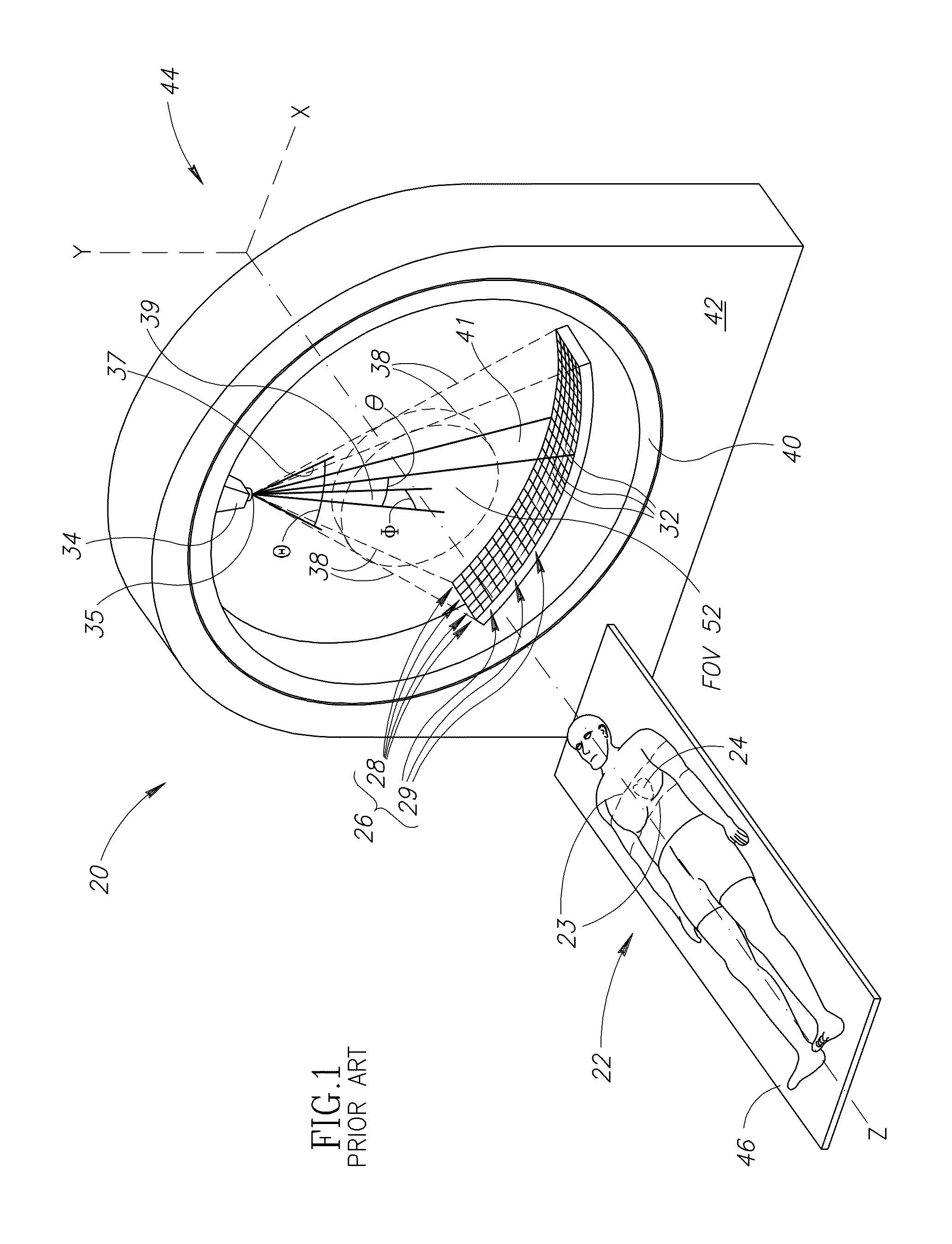
[0042]FIG. 1 schematically shows a multislice CT scanner 20 for imaging patients, in accordance with prior art. In FIG. 1 a patient 22 having an imaging region indicated by dashed lines 23 and a localized region of interest LROI 24 within the imaging region shown in dashed lines is to be imaged with scanner 20. LROI 24 is by way of example, the patient's heart. Only features of multislice scanner 20 germane to the discussion of the present invention are shown in FIG. 1.

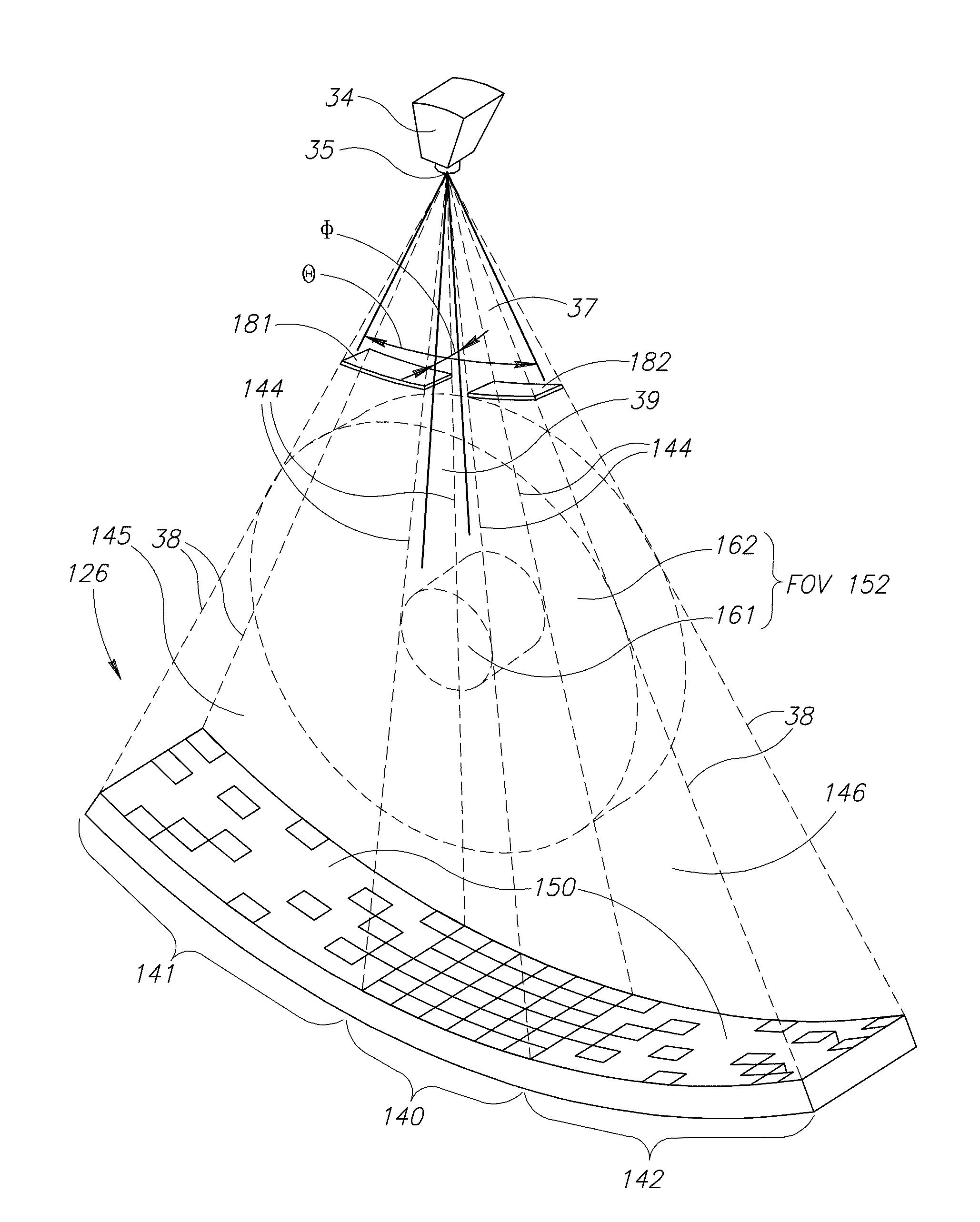
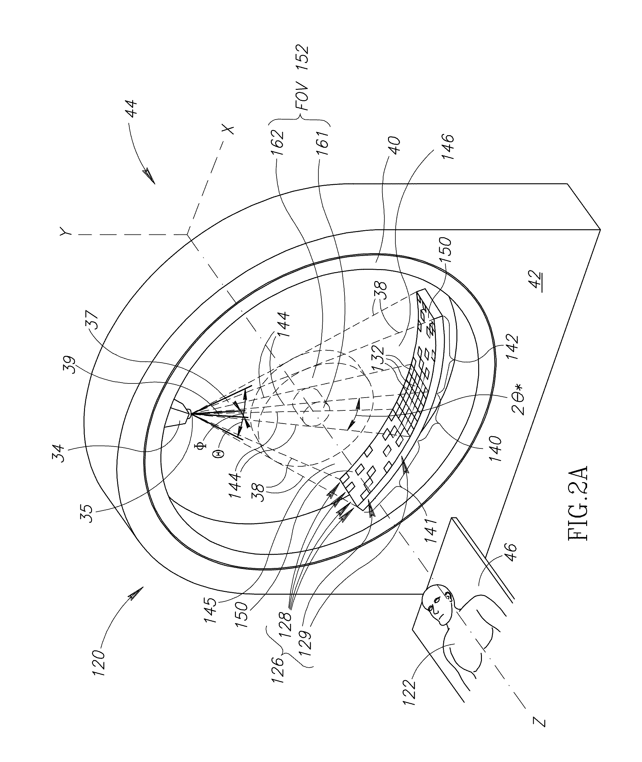
[0043]Multislice scanner 20 comprises a detector array 26 of X-ray detectors 32 and an X-ray source 34 that provides a cone beam of X-rays shown in dashed lines 38 for illuminating patient 22 with X-rays. Cone beam 38 emanates from a focal spot 35 of X-ray source 34. X-ray source 34 and detector array 26 are mounted to a rotor 40 of a gantry 42. Rotor 40 is rotatable around the z-axis of a coordinate system 44.

[0044]Detectors 32 in detector array 26 are configured in rows 28 and columns 29 of detectors 32 so that each...


PUM

PropertyMeasurementUnit
distanceaaaaaaaaaa
diameteraaaaaaaaaa
diameteraaaaaaaaaa

Abstract

A CT scanner comprising: a rotor rotatable about an axis of rotation: an X-ray source mounted to the rotor having a focal spot from which an X-ray beam emanates; an X-ray detector array comprising a plurality of X-ray detectors for detecting X-rays in the X-ray beam; wherein the detector array has at least one high resolution region in which detectors have a high packing density and at least one low resolution region in which detectors have a low packing density and are separated by X-ray insensitive regions substantially larger than insensitive regions resulting from septa between detectors that function to reduce detector cross talk.

Description

RELATED APPLICATIONS[0001]This Application is a National Phase of PCT Patent Application No. PCT / IB2006 / 051737 having International Filing Date of May 31, 2006, which claims benefit under USC 119(e) of U.S. Application No. 60 / 685,418 filed on May 31, 2005 entitled “CT Scanner and Method for Medical Imaging, Particularly Useful for Imaging of the Human Heart”, the disclosure of which is incorporated herein by reference.FIELD OF THE INVENTION[0002]The present invention relates to computerized tomography (CT) X-ray imaging and to CT scanners having fields of view (FOVs) adapted for imaging limited volumes of tissue within a patient's body.BACKGROUND OF THE INVENTION[0003]In CT X-ray imaging of a patient, X-rays are used to image internal structure and features of a region, an “imaging region”, of the patient's body. The imaging is performed by a CT scanner comprising an X-ray source that provides an X-ray beam and an array of closely spaced X-ray detectors facing a region, referred to ...

Claims


Application Information

Patent Timeline
Patent Type & Authority Patents(United States)
IPC IPC(8): G01N23/00
CPCA61B6/032G01N23/046G01T1/24G01T1/249G01T1/2985G01N2223/612G01N2223/419A61B6/4208A61B6/4233
Inventor DAFNI, EHUD
Owner ARINETA
Why Eureka
Try Eureka