

Control system design method
a control system and design method technology, applied in the direction of electric controllers, instruments, controllers with continuous output signals, etc., can solve problems such as limiting the maximum potential of the system
- Summary
- Abstract
- Description
- Claims
- Application Information
AI Technical Summary
Benefits of technology
Problems solved by technology
Method used
Image

Examples
example 1
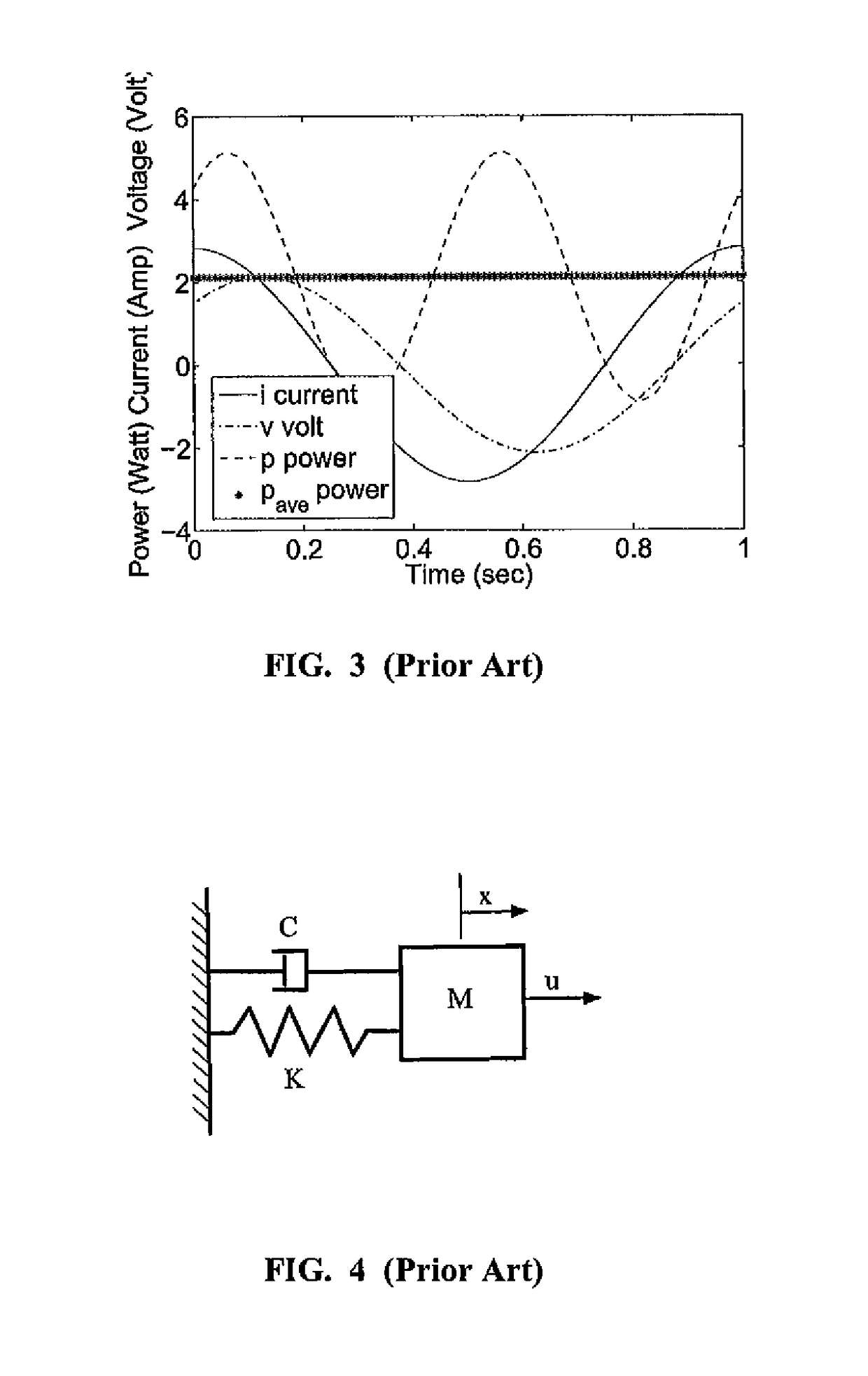
[0126]The dynamic equation of motion for a forced harmonic oscillator (see FIG. 4) is defined as
M{umlaut over (x)}+C{umlaut over (x)}+Kx=Fo cos Ωt. (22)
The steady-state response has the form
xp=X cos(Ωt−φ) (23)
Substitute (23) into (22) and solve for X which produces
[0127]X=Fo / K[1-(Ωωn)2]2+[2ζ(Ωωn)]2whereωn2=KM,ζ=C / 2Mωnandtanφ=2ζ(Ωωn)1[1-(Ωωn)2].
Also note that for a static deflection Xo=Fo / K, where the dynamic magnification factor becomes
[0128]H(Ω)=XXo=11-r2wherer=Ωωnforζ=0.
For r=1 or Ω=ωn, the response is undefined or unstable. This is shown conventionally with the Bode plot (see FIG. 12).
[0129]The forced harmonic oscillator dynamic model instability can also be predicted with exergy / entropy control. Applying the exergy / entropy control design (for power input or exergy generation rate only) gives
[0130]V.=W.-ToS.i=∑j=1NQjq.j-∑l=NM-NQlq.l=W.=Qq..
Then by applying the following definitions for Q and {dot over (q)} at Ω=ωn, φ=π / 2, and ζ=0 gives
Q=...
example 2
[0139]The mass-spring-damper dynamic model (see FIG. 4) is defined as
M{umlaut over (x)}+C{dot over (x)}+Kx=u (25)
where M, C, K, and u are the mass, damper, stiffness coefficients and external force input terms. The Proportional-Derivative (PD) and Proportional-Integral-Derivative (PID) controller is defined as
[0140]u=-KPx-KI∫0txⅆτ-KDx.(26)
where Kp, KI, and KD are the proportional, integral and derivative controller gains. Also note that for PD control, KI=0.0.
[0141]The passive PD control law is partitioned into terms of exergy dissipation and exergy generation. Now apply exergy / entropy control design and the time derivative of the Lyapunov function / Hamiltonian becomes
[0142]V.=H.=W.-ToS.i=∑j=1NQjq.j-∑l=NM-NQlq.l(27)
which yields
To{dot over (S)}i=(C+KD){dot over (x)}·{dot over (x)}
{dot over (W)}=0
(To{dot over (S)}rev)ave=(M{umlaut over (x)}·{dot over (x)}+(K+KP)x·{dot over (x)})ave=0. (28)
[0143]The first term in (28) is identified as a dissipative term composed of the de...
example 3
[0175]This example is the design of a control law for a single degree of freedom nonlinear oscillator. The Duffing oscillator / Coulomb friction dynamic model (see FIG. 22) is defined as
M{umlaut over (x)}+C{dot over (x)}+CNL sign({dot over (x)})+Kx+KNLx3=u (33)
where M, C, K, and u are the mass, damper, stiffness coefficients and external force input terms. The nonlinear stiffness and Coulomb friction coefficients are KNL and CNL, respectively. The PID controller is defined as
[0176]u=-Kpx-KI∫0txⅆτ-KDx.(34)
where KP, KI, and KD are the proportional, integral and derivative controller gains.
[0177]Initially, the nonlinear Duffing oscillator is investigated as a neutrally stable, reversible conservative system or
M{umlaut over (x)}+Kx+KNLx3=−KPx
subject to the initial condition x(0)=xo=1.0. Now apply exergy / entropy control design and the derivative of the Lyapunov function / Hamiltonian becomes
[0178]V.=H.=W.-ToS.i=∑j=1NQjq.j-∑l=NM-NQlq.l(35)
which yields
To{dot over (S)}i=0
{dot ove...
PUM
 Abstract
Description
Claims
Application Information