Total in place hydrocarbon recovery by isolated liquid and gas production through expanded volumetric wellbore exposure +

a technology of isolated liquid and hydrocarbon recovery, which is applied in the direction of fluid removal, earth-moving drilling, borehole/well accessories, etc., can solve the problems of unrecoverable or becoming unrecoverable, the vast majority of the world's oil reserves are critically losing solution gas saturation, and the natural gas recovery worldwide is critically decreasing, so as to achieve efficient lifting to the surface and pressure differential flow

Inactive Publication Date: 2012-02-28
KELLEY TERRY EARL
View PDF3 Cites 15 Cited by
  • Summary
  • Abstract
  • Description
  • Claims
  • Application Information

AI Technical Summary

Benefits of technology

[0026]World oil reserves have from the oil Industries beginning been critically losing solution gas saturation due to the world oil industry's long-established oil producing methods by flowing oil with gas. Thus allowing solution gas break out from the oil, leaving the much greater majority of the World's oil reserves unrecoverable or becoming unrecoverable, often as high as 80%. While in numerous, and particularly in established and / or mature producing natural gas reservoirs, natural gas recovery worldwide is critically decreasing due to incoming liquids (water, oil, and / or condensate) interference or blockage to gas production flow. The present invention gives effectual solutions to these currently threatening world oil and gas supply problems, to now recover very close to total in place oil in average to high gravity oil reservoirs, and total in place natural gas in liquid burdened gas reservoirs by the present invention's addition of maximally increased O.D. size vertical boreholes and increased O.D. size horizontally and length boreholes, lined with expandable liners and sand screens, for significantly increased crude oil and / or natural gas recovery through maximum volumetric exposure. And by producing gas formation liquid hydrocarbons (or waters) and gaseous hydrocarbons though separate conduits to the surface. And by controllably marinating solution gas saturation and gas pressure in crude oil formations. Thus both liquid and gaseous hydrocarbon recovery systems of the present invention benefit from maximum volumetric exposure to liquid and / or gaseous hydrocarbons for increased volumetric recovery from a given formation area at a greater than before augmented production rate.
[0048]Hence the present invention discloses novel systems and methods to recover primary secondary and / or unrecoverable total in place oil, as well as primary, secondary gas; or water, oil and / or condensate blocked gas; to recover total in place oil and natural gas in reservoirs where applicable worldwide, notably increasing total in place recovery from and lengthening US and world oil and gas reservoir oil and gas recovery numerous decades.

Problems solved by technology

World oil reserves have from the oil Industries beginning been critically losing solution gas saturation due to the world oil industry's long-established oil producing methods by flowing oil with gas.
Thus allowing solution gas break out from the oil, leaving the much greater majority of the World's oil reserves unrecoverable or becoming unrecoverable, often as high as 80%.
While in numerous, and particularly in established and / or mature producing natural gas reservoirs, natural gas recovery worldwide is critically decreasing due to incoming liquids (water, oil, and / or condensate) interference or blockage to gas production flow.

Method used


Image

  • Total in place hydrocarbon recovery by isolated liquid and gas production through expanded volumetric wellbore exposure +
  • Total in place hydrocarbon recovery by isolated liquid and gas production through expanded volumetric wellbore exposure +
  • Total in place hydrocarbon recovery by isolated liquid and gas production through expanded volumetric wellbore exposure +

Examples


Embodiment Construction

”.

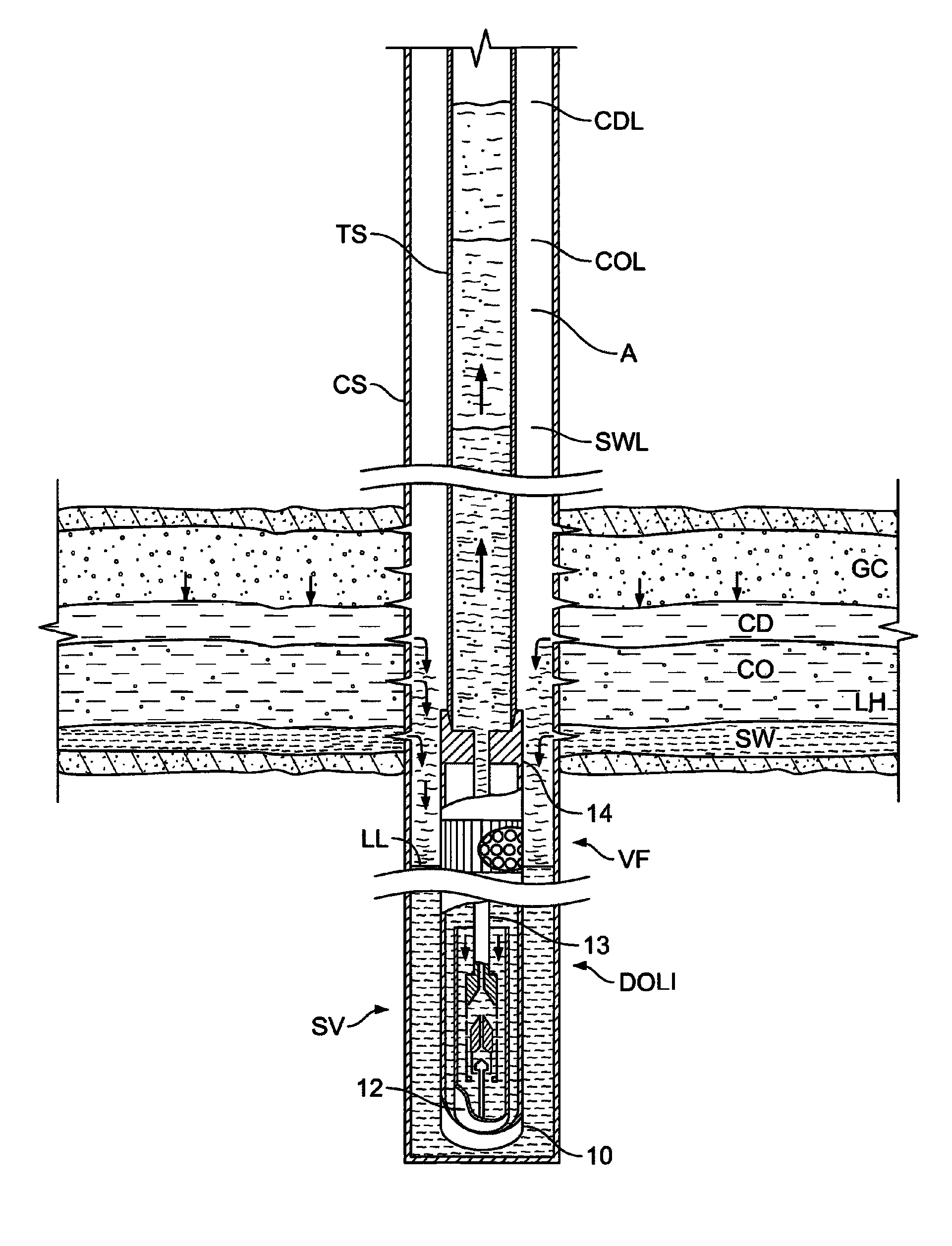
[0054]FIG. 4 illustrates an example of how various natural gas or liquid hydrocarbon formation liquids, condensate CD, crude oil CO, and salt water SW, flow downward in the wellbore to fill and open the present invention's, Liquid Injector's float, where they are injected by wellbore to production tubing pressure differential toward the surface in that production tubing string. Relative liquid levels, condensate level CDL, crude oil level COL, and salt water level SWL, that a given operating bottom hole wellbore pressure would lift each liquid through the Liquid Injector's float according to its static gradient, are shown for illustration of the Liquid Injector's static liquid lifting abilities. When needed, the invention's artificial lift methods are applied to lift these liquids to surface.

[0055]FIG. 5 illustrates the present invention's Liquid Injector's alternative extended length float EFS, required when excessively high formation to wellbore pressure, and minimum tubing pres...


PUM


Abstract

Higher volumetric hydrocarbon exposed original or restored by miscible gas injection, solution gas saturated oil is recovered through enlarged expandable liner, sand screened wellbores by controlled wellbore to formation pressure maintained above recovering oils critical bubble point. Exclusively hydrocarbon formation liquids are differential pressure forced through centralizer held larger outer diameter liquid displacer into the production tubing, while maintaining gas volume, pressure, and solution gas saturation in the formation, for higher volume flow for total in place oil recovery. Injected downstructure waterdrive pressure (WDP) into oil or gas formations augments oil and / or gas production and recovery. Complete gas well de-liquefying is attained by flowing gas recovery through enlarged expandable liner and sand screened wellbores and up the wellbore annulus dry, while producing all liquids separately through the larger outer diameter liquid displacer into the production tubing, to be artificial lifted to surface, while waterdrive pressure (WDP) augments natural gas recovery.

Description

FIELD OF INVENTION[0001]The present invention relates to an obtained increased expanded volumetric exposure area in gaseous or liquid hydrocarbon formations and its sophisticated centralized and increased outside diameter (O.D.) Downhole Liquid Displacer (DLD) tool's wellbore system for recovering total in place crude oil, and / or condensate, while natural gas is maintained in the reservoir for gas drive pressure or produced. The inventions unique separate liquid and gaseous hydrocarbon recovery is benefited by this enlarged volumetric exposed area to in place liquid and / or gaseous hydrocarbons by means of larger O.D. vertical and optional horizontal boreholes, sealed off with an expandable perforated liner, optionally screened from sand influx. This significantly enhanced volumetric exposure area allows for increased volume flow of liquid hydrocarbons and / or liquid free natural gas production for total in place available oil and / or gas recovery, producing total incoming formation li...

Claims


Application Information

Patent Timeline
Patent Type & Authority Patents(United States)
IPC IPC(8): E21B43/16
CPCE21B43/122E21B43/14E21B43/168E21B43/305
Inventor KELLEY, TERRY EARL
Owner KELLEY TERRY EARL
Why Eureka
Try Eureka