Rotational, shear mode, piezoelectric motor integrated into a collocated, rotational, shear mode, piezoelectric micro-actuated suspension, head or head/gimbal assembly for improved tracking in disk drives and disk drive equipment

a micro-actuation and disk drive technology, applied in the field of motors, can solve the problems of insufficient collocation alone, insufficient resolution and frequency response of actuators, and limitations of vcm actuators, etc., to achieve the effect of improving data storage capacity, improving fine track positioning, and increasing track density

Active Publication Date: 2012-02-28
MAGNECOMP +1
View PDF24 Cites 59 Cited by
  • Summary
  • Abstract
  • Description
  • Claims
  • Application Information

AI Technical Summary

Benefits of technology

[0057]A rotational, shear mode, piezoelectric motor is integrated into a collocated, rotational, shear mode, piezoelectric micro-actuated suspension, head or HGA for disk drives and disk drive equipment. When used in a disk drive system with dual stage actuation, the collocated, rotational, shear mode piezoelectric micro-actuated HGA provides fine track positioning and contributes toward higher track densities and higher data storage capacity. The present invention of a collocated, rotational, shear mode piezoelectric micro-actuated HGA has application in disk drives, disk certifiers, disk servo writers and dynamic head testers that require improved fine track positioning.

Problems solved by technology

Errors in the circular shape are due to spindle run-out, vibration modes from the numerous mechanical components of the disk drive, windage, acoustic noise and many interactions thereof.
As track density increases, VCM actuators have limitations in resolution and frequency response.
These actuators suffer from insufficient frequency response at the head due to the low stiffness over the long distance between the micro-actuator and the head.
These designs suffer because they tend to distort the air bearing surface of the slider.
However, collocation alone is insufficient to make a robust micro-actuator for disk drives.
While the micro-actuator itself may be mechanically stiff and provide high frequency response, the suspension is not mechanically stiff on the transverse axis.
Lack of stiffness reduces the frequency response of the system.
While rotation about the exact center of mass of the head is improbable, it is understood that the closer the rotation axis is to the head's center of mass, the smaller a disturbance is created in the suspension.
The middle section of the piezoelectric beam that is free to expand and contract is mechanically unsupported and therefore is less robust to shock and vibration.
Mishandling or a large shock can fracture the brittle piezoelectric beam.
Another disadvantage arises when the desired axis expands and contracts, specifically, a secondary axis respectively contracts and expands.
This secondary axis of actuation can lead to undesired displacement and vibration.
These piezoelectric motors also have an undesirable property that moderate reverse voltages can depolarize the piezoelectric motor.
However several deficiencies arise when longitudinal or transverse mode piezoelectric micro-actuator 60 is used in a disk drive 1.
As a result, the unbalanced stress from expansion bends both the stainless steel hinges 82 and the piezoelectric beam 51.
Small adhesive areas promote the free expansion and contraction of piezoelectric beam 51, yet the unsupported regions are more susceptible to unwanted vibration.
The second disadvantage is that a collocated, transverse displacement design does not provide mechanical advantage.

Method used


Image

  • Rotational, shear mode, piezoelectric motor integrated into a collocated, rotational, shear mode, piezoelectric micro-actuated suspension, head or head/gimbal assembly for improved tracking in disk drives and disk drive equipment
  • Rotational, shear mode, piezoelectric motor integrated into a collocated, rotational, shear mode, piezoelectric micro-actuated suspension, head or head/gimbal assembly for improved tracking in disk drives and disk drive equipment
  • Rotational, shear mode, piezoelectric motor integrated into a collocated, rotational, shear mode, piezoelectric micro-actuated suspension, head or head/gimbal assembly for improved tracking in disk drives and disk drive equipment

Examples


Embodiment Construction

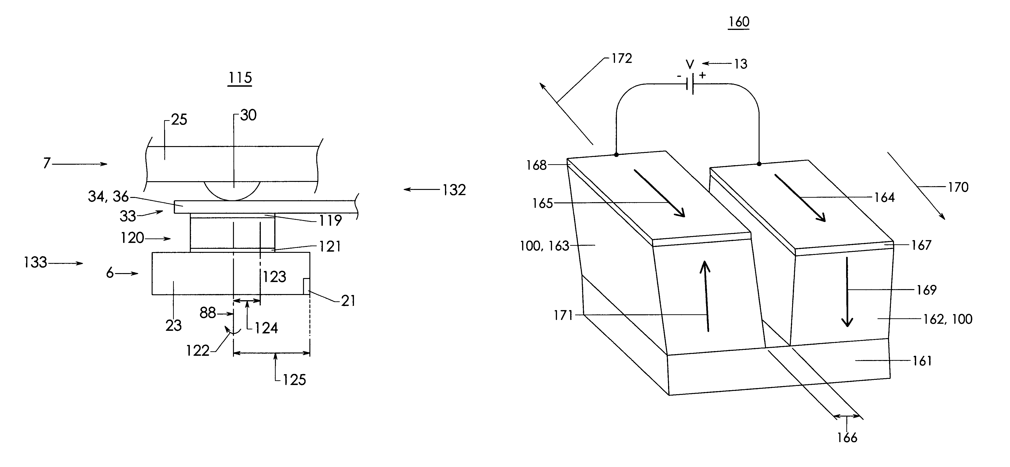
[0083]For the present invention, shear mode piezoelectric material 101 may come from sources other than commercially available bulk materials. Custom compositions and processing techniques may be needed to improve performance or miniaturize the shear mode piezoelectric motor 100. For instance, thin film deposition and etching techniques may be more appropriate for creating increasingly small motor patterns or increasingly thin stacked layers in high volume.

[0084]As used herein, the term “collocated” micro-actuator includes one that is bonded to the flexure assembly 33 at the flexure tongue 36, one that is bonded to the head 6, or one that is bonded to both the head 6 and the flexure assembly 33 at the gimbal tongue 36. Thus, a collocated micro-actuator does not strictly need to be located “between” head 6 and flexure assembly 33, as in the case where a micro-actuator may have some physical presence above the flexure 33 or beside head 6. Thus, as seen in FIG. 8, micro-actuator 120 is...


PUM

PropertyMeasurementUnit
thicknessaaaaaaaaaa
radiusaaaaaaaaaa
radiusaaaaaaaaaa

Abstract

A rotational, shear mode, piezoelectric motor is integrated with a suspension, head or head gimbal assembly (HGA) into a collocated, rotational, shear mode, piezoelectric micro-actuated suspension, head or head gimbal assembly (HGA) for use in disk drives and disk drive manufacturing equipment. When excited by a control voltage, the collocated, shear mode, piezoelectric micro-actuated HGA rotates the head enabling high frequency, high resolution track positioning of the read / write element. The motor is integrated with the head and flexure (collocation). The head rotates about a rotation axis that is ideally located at the center of mass of the head. A shear mode piezoelectric motor rotates the head. A collocated, rotational, shear mode, piezoelectric micro-actuated HGA has high stiffness, high frequency response, high positioning resolution, low mass and low internal vibration for improved tracking, increased track density and greater disk drive storage capacity. Furthermore, its solid integration improves shock resistance and reduces micro-contamination.

Description

FIELD OF THE INVENTION[0001]The present invention relates to a motor and more specifically to data storage technology including a read / write head, a slider, a suspension, a head gimbal assembly, a read / write head positioning mechanism, an actuator, a micro-actuator and data storage devices such as a magnetic disk drive and an optical disk drive, and finally the equipment used to manufacture and test components of said disk drives, including but not limited to, disk certifiers, disk servo writers and dynamic electrical head testers.BACKGROUND ART[0002]Increasing storage capacity is a goal in the data storage industry. Data storage products such as magnetic disk drives and optical disk drives, store digital information on rotating disks using a read / write head. The information is typically recorded in concentric, circumferential tracks about the near-center of the disk. One method to increase data storage capacity is to increase track density, where track density is defined as the num...

Claims


Application Information

Patent Timeline
Patent Type & Authority Patents(United States)
IPC IPC(8): G11B21/02G11B5/596
CPCG11B5/4826G11B5/4873H01L41/0993G11B5/5552G11B5/483H10N30/208
Inventor SHELOR, JOHN R.
Owner MAGNECOMP
Why Eureka
Try Eureka