Transonic airfoil and axial flow rotary machine

a rotary machine and axial flow technology, applied in supersonic fluid pumps, machines/engines, climate sustainability, etc., can solve the problems of profile loss and secondary loss, loss due, loss due, etc., to reduce the loss of tip leakage, strengthen the separation resistance of the hub, and weaken the shock wave

Active Publication Date: 2012-03-13
MITSUBISHI POWER LTD
View PDF10 Cites 14 Cited by
  • Summary
  • Abstract
  • Description
  • Claims
  • Application Information

AI Technical Summary

Benefits of technology

[0008]As described above, in the rotor airfoil described in Patent Document 1, the interference of the secondary flow resulting from the tip leakage with the shock wave is alleviated and the loss of the tip is reduced, by forming the upstream of the rotor airfoil leaning forward. Accordingly, the flow is sent to the tip to enhance the efficiency of the tip, while the boundary layer of the hub (base) is thickened and thus the flow is unstable, thereby reducing the efficiency of the hub.Means for Solving the Problem
[0009]In view of the above-mentioned problems, an object of the invention is to provide a transonic airfoil and an axial flow rotary machine that can suppress the reduction in efficiency due to the shook wave on the tip and avoid enlargement of a boundary layer of a hub, thereby preventing separation.
[0015]According to the above-mentioned aspect of the invention, by forming the S shape in which the tip and the part between the hub and the midportion are shifted to the upstream, the boundary layer of the hub can be decreased in thickness to enhance the separation resistance of the hub and the boundary layer of the tip can be increased in thickness to reduce the tip leakage loss. Since the tip protrudes to the upstream, it is possible to weaken the shock wave, thereby suppressing various losses due thereto. Because of the decrease in loss, it is possible to efficiently transmit rotary energy of the airfoil to the fluid. By reducing the separation of the airfoil, it is possible to enhance the stall margin.

Problems solved by technology

In an axial flow rotary machine having the transonic airfoils and operating by the transonic or supersonic operating fluid, a shook wave is generated due to the compressibility of the operating fluid and various losses such as profile loss and secondary loss are caused.
That is, a loss due to the shock wave itself, a loss due to interference of the shock wave with the solid wall boundary layer, and a loss due to interference of the shock wave with a tip clearance leakage (a leakage from a clearance between an airfoil tip and a casing due to a pressure difference between a suction surface and a pressure surface) of the airfoil are generated.
When the angle of incidence increases, pressure loss also increases, thereby lowering the efficiency in the axialflow rotary machine.

Method used


Image

  • Transonic airfoil and axial flow rotary machine
  • Transonic airfoil and axial flow rotary machine
  • Transonic airfoil and axial flow rotary machine

Examples


first embodiment

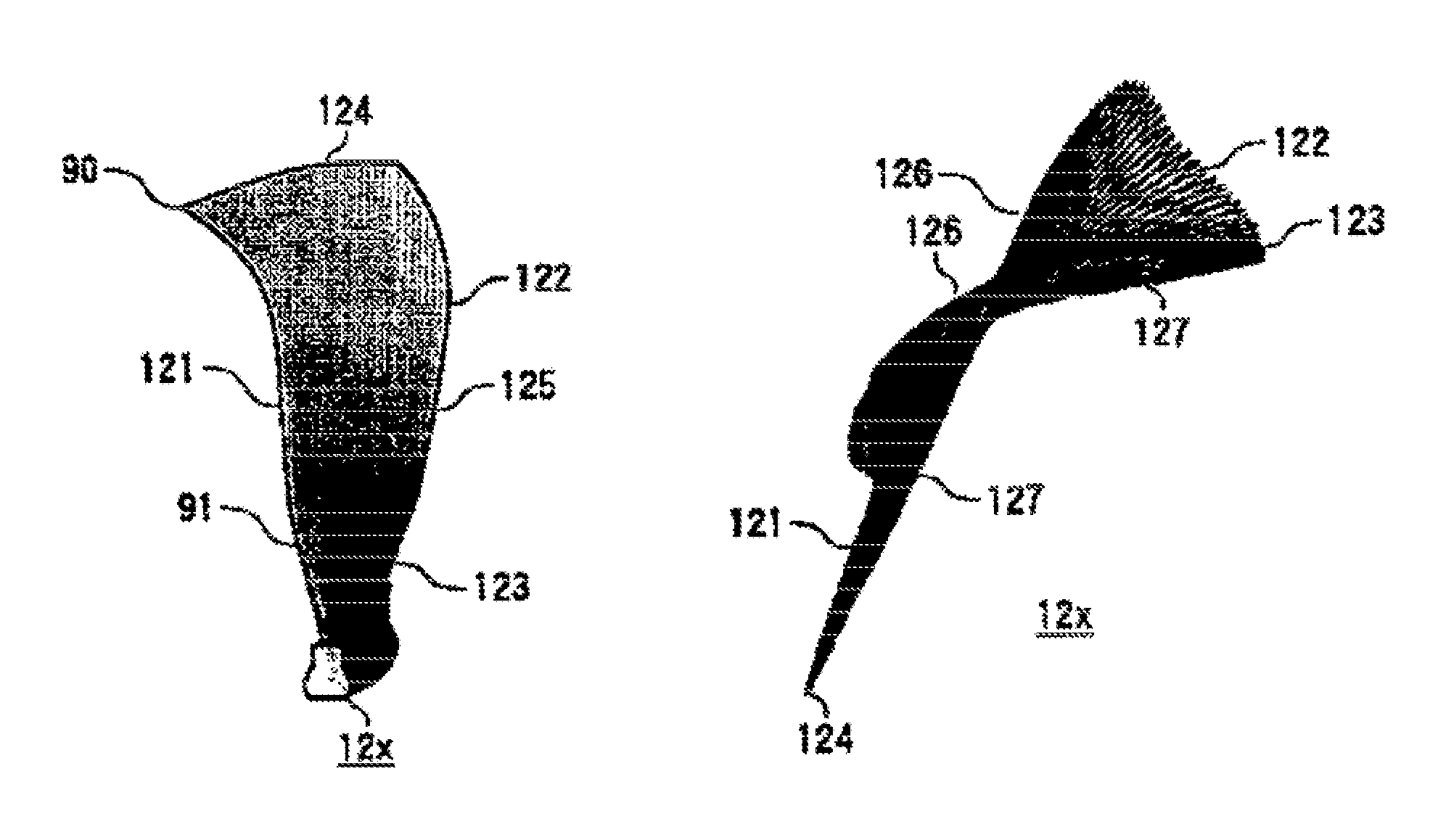
[0077]A transonic airfoil according to a first embodiment in which the sectional profiles in the span direction are adjusted in the sweep direction will be described with reference to the drawings on the basis of the above-mentioned basic configuration. FIG. 9 is a perspective view schematically illustrating a configuration of a transonic airfoil according to the present embodiment. FIG. 10 is a diagram illustrating the shift in the sweep direction of the sectional profiles in the span direction from the hub to the tip.

[0078]As shown in FIG. 9, a transonic airfoil 12x according to the present embodiment has a shape obtained by combining the forward swept shape of the transonic airfoil 12b shown in FIG. 5B with the backward swept shape of the transonic airfoil 12c shown in FIG. 5C. That is, the transonic airfoil 12x shown in FIG. 9 has a shape in which the sectional profiles close to the tip 124 are shifted to protrude to the upstream in the sweep direction, similarly to the forward ...

second embodiment

[0083]A transonic airfoil according to a second embodiment in which the sectional profiles in the span direction are adjusted in the sweep direction will be described with reference to the drawings on the basis of the above-mentioned basic configuration. In the present embodiment, similarly to the transonic airfoil according to the first embodiment, in addition to the configuration in which the sectional profiles in the span direction are adjusted in the sweep direction, the positions of the sectional profiles are changed in the lean direction and the sectional profiles are stacked.

[0084]That is, in the transonic airfoil 12y according to the present embodiment, similarly to the transonic airfoil 12x according to the first embodiment, the sectional profiles in the span direction from the hub to the tip are shifted in the sweep direction so that the tip 124 has the forward swept shape and the hub 123 has the backward swept shape. In addition, the sectional profiles in the span directi...


PUM


Abstract

Sectional profiles close to a tip 124 and a part between a midportion 125 and a hub 123 are shifted to the upstream of an operating fluid flow in a sweep direction. Accordingly, an S shape is formed in which the tip 124 and the part between the midportion 125 and the hub 123 protrude. As a result, it is possible reduce various losses due to shook, waves, thereby forming a transonic airfoil having an excellent aerodynamic characteristic.

Description

[0001]This application is a 371 of international application No. PCT / JP2007 / 067645 filed on Sep. 11, 2007, and claims priority of Japanese application No. 2006-298841, filed on Nov. 2, 2006.TECHNICAL FIELD[0002]The present invention relates to a transonic airfoil operating in a transonic or supersonic flow region and an axial flow rotary machine such as a turbine having the transonic airfoil, and more particularly, to a transonic airfoil having a three-dimensional shape and an axial flow rotary machine having the transonic airfoil.BACKGROUND ART[0003]In axial flow rotary machines such as a gas turbine, an aircraft fan engine, and an aircraft jet engine, losses generated in an airfoil cascade can be roughly classified into profile loss due to airfoil shape itself and secondary loss due to fluid flowing between the airfoil cascades. A rotor airfoil suppressing a secondary flow in a solid wall boundary layer generating in an airfoil surface by arranging a higher position of a leading e...

Claims


Application Information

Patent Timeline
Patent Type & Authority Patents(United States)
IPC IPC(8): F01B25/02
CPCF01D5/141F04D21/00F04D29/324Y02T50/673F05D2220/36F05D2250/713Y02T50/60F04D29/38F04D29/66
Inventor NAGAI, NAONORIIWATANI, JUNJI
Owner MITSUBISHI POWER LTD
Why Eureka
Try Eureka