GMR biosensor with enhanced sensitivity

a biosensor and enhanced technology, applied in the field of detection of small magnetized particles, can solve the problems of adverse effects, lack of reproducibility, negative hysteresis effect, etc., and achieve the effects of enhancing detectability, stable bias point, and adverse hysteresis

Active Publication Date: 2012-03-13
APPLIED SPINTRONICS +1
View PDF13 Cites 5 Cited by
  • Summary
  • Abstract
  • Description
  • Claims
  • Application Information

AI Technical Summary

Benefits of technology

[0021]A fourth object of the present invention is to provide a GMR sensor to be used in detecting the presence of small magnetized particles wherein the response of the sensor to external magnetic fields is not adversely affected by a non-reproducibility of its free layer bias point due to magnetic hysteresis.
[0022]A fifth object of the present invention is to provide a GMR sensor having a high sensitivity and a free layer bias point that is reproducible.
[0024]6. The structure of each individual stripe is a capped lamination (see FIG. 4b) comprising a free layer (99) and a pinned layer (77) separated by a metallic spacer layer (88), wherein the pinned layer can be a synthetic layer for enhanced pinning strength. The stripes are surrounded by insulating layers (45).7. The magnetic anisotropy of each stripe is reduced by minimizing its free layer thickness and providing a minimal interlayer coupling between the free and pinned layers.8. The free layer thickness is minimized, while not degrading the stripe's dR / R.9. The interlayer coupling is minimized by adjusting the thickness of the metallic layer separating the free and pinned layers.10. The film magnetostriction can be adjusted, in conjunction with an overcoat stress, to produce a net stress-induced anisotropy. With proper combination of these two stress factors, the easy axis of the stress-induced anisotropy can be oriented perpendicular to the longitudinal direction of the stripe, so as to cancel out the free layer shape anisotropy.
[0025]The characteristics enumerated above will produce a sensor having a reproducible bias point while still retaining a free layer magnetization that is responsive to the effects of small external magnetic fields. In particular, by orienting the bias direction along the lengthwise direction of the sensor stripe, the adverse hysteresis effects on a stable bias point will be offset by the shape anisotropy produced by a stripe shape that is longer than it is wide. By a combination of magnetostriction and stress-induced anisotropy that is perpendicular to the shape anisotropy, however, the overall magnetization remains responsive and the sensor is sensitive to small external fields. In addition, by forming a narrow space (less than bead diameter) between adjacent stripes in an array, making the width of the stripes comparable to the dimensions of the bead and by orienting adjacent sensor stripes parallel to each other, the position of a magnetic particle is likely to overlap two adjacent stripes, thereby, having its detectability enhanced by the series response of two stripes.

Problems solved by technology

The issue, then, is to provide an effective method of detecting the small magnetic beads, since the detection of the beads is tantamount to detection of the target molecules.
This hysteresis has a negative impact on the reproducibility of sensor readings, particularly when the external stimuli moving the free layer magnetization are small to begin with.
The methods cited above that rely on the use of a GMR sensor, rather than methods such as inductive sensing or Hall effect sensing, will all be adversely affected by the failure of the GMR sensor to maintain a reproducible bias direction for its free layer magnetization.
This lack of reproducibility is a result of magnetic hysteresis that occurs whenever the external magnetic fields being detected cause the magnetic moment of the sensor free layer to cycle about its bias direction.
Because of this, methods to fix the bias point of the sensor free layer cannot fix it too strongly as this would limit the ability of the free layer magnetic moment to respond to the very stimuli it is attempting to measure.

Method used


Image

  • GMR biosensor with enhanced sensitivity
  • GMR biosensor with enhanced sensitivity
  • GMR biosensor with enhanced sensitivity

Examples


Embodiment Construction

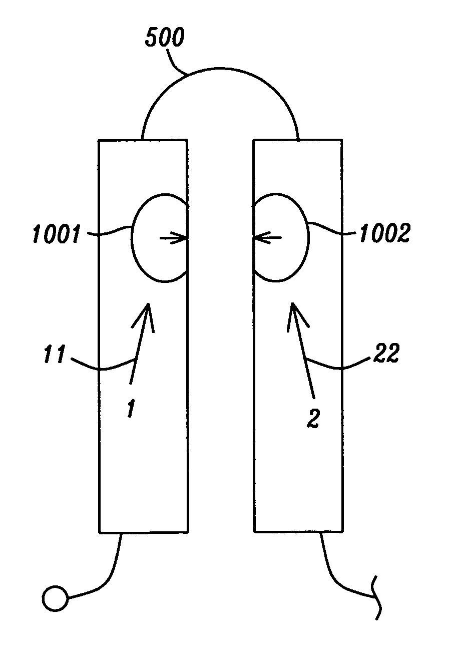
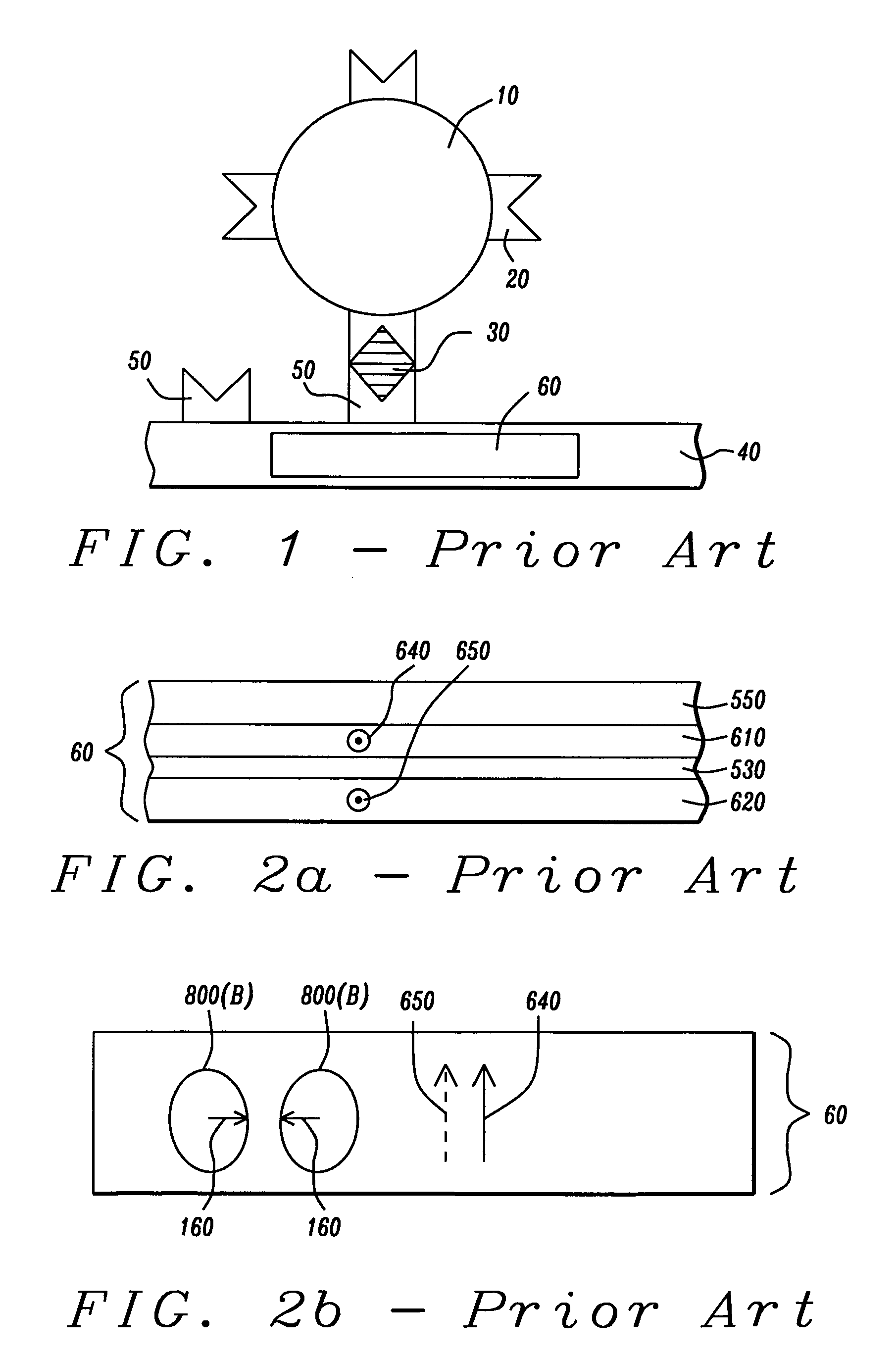
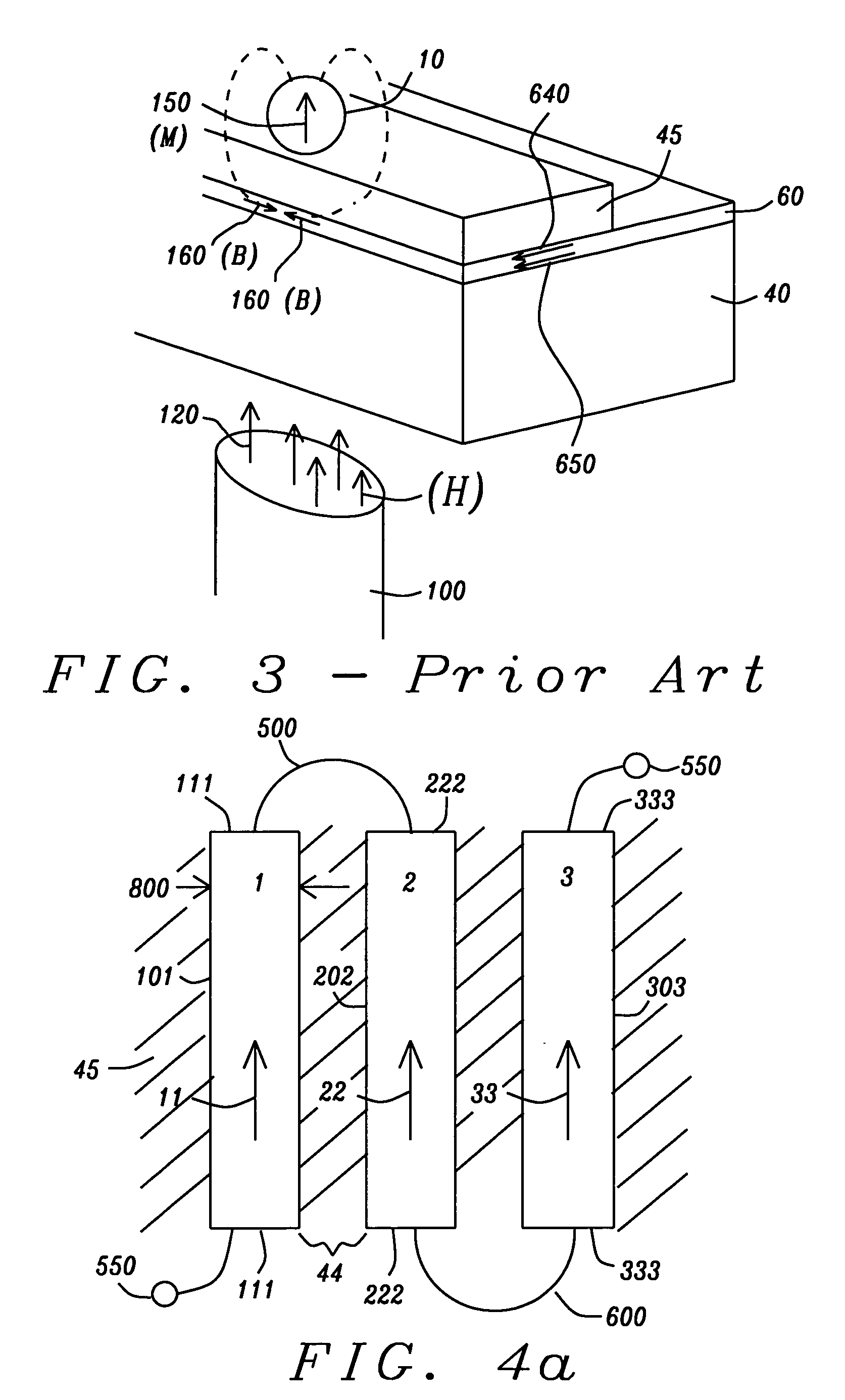
[0034]The preferred embodiments of the present invention are a GMR sensor stripe and an array of such GMR sensor stripes, capable of detecting the presence of magnetic particles or beads, typically bonded to chemical molecules. The GMR stripe and the array of stripes, by virtue of their formation, are not adversely affected by instability of a free layer bias point due to hysteresis. We use the term “stripe” to characterize a GMR sensor element and to emphasize the fact that it is deposited in the shape of a long, approximately rectangular strip or stripe. When used to detect magnetic particles bonded to target molecules (eg. in a bio-chemical assay) the array is formed beneath a surface on which are affixed bonding sites for target molecules. To perform the detection process, the target molecules whose presence is to be detected, as well as others that are not targets, are first magnetically tagged, by being bonded to small magnetic particles or beads that are subsequently magnetiz...


PUM

PropertyMeasurementUnit
thicknessaaaaaaaaaa
thicknessaaaaaaaaaa
thicknessaaaaaaaaaa

Abstract

A sensor array comprising a series connection of parallel GMR sensor stripes provides a sensitive mechanism for detecting the presence of magnetized particles bonded to biological molecules that are affixed to a substrate. The adverse effect of hysteresis on the maintenance of a stable bias point for the magnetic moment of the sensor free layer is eliminated by a combination of biasing the sensor along its longitudinal direction rather than the usual transverse direction and by using the overcoat stress and magnetostriction of magnetic layers to create a compensatory transverse magnetic anisotropy. By making the spaces between the stripes narrower than the dimension of the magnetized particle and by making the width of the stripes equal to the dimension of the particle, the sensitivity of the sensor array is enhanced.

Description

BACKGROUND OF THE INVENTION[0001]1. Field of the Invention[0002]This invention relates to the detection of small magnetized particles (beads) by a GMR sensor, particularly when such particles or beads are attached to molecules whose presence or absence is to be determined in a chemical or biological assay.[0003]2. Description of the Related Art[0004]GMR (giant magnetoresistive) devices have been proposed as effective sensors to detect the presence of specific chemical and biological molecules (the “target molecules”) when, for example, such target molecules are a part of a fluid mixture that includes other molecules whose detection is not necessarily of interest. The basic method underlying such magnetic detection of molecules first requires the attachment of small magnetic (or magnetizable) particles (also denoted “beads”) to all the molecules in the mixture that contains the target molecules. The magnetic beads are made to attach to the molecules by coating the beads with a chemic...

Claims


Application Information

Patent Timeline
Patent Type & Authority Patents(United States)
IPC IPC(8): G01N15/06
CPCB82Y25/00G01N27/745G01R33/098G01R33/093G01N15/0656Y10T29/49986Y10T29/49124G01R33/05G01N2015/0065G01R33/0052
Inventor WANG, PO-KANGSHI, XIZENGTORNG, CHYU-JIUH
Owner APPLIED SPINTRONICS
Why Eureka
Try Eureka