Cooling system for a variable vacuum capacitor

a vacuum capacitor and cooling system technology, applied in the direction of variable capacitors, lighting and heating apparatus, electrical apparatus construction details, etc., can solve the problems of excessive heat energy produced in the metal bellows, distilled or de-ionized water must be used, and the requirement is difficult to achieve, so as to achieve good heat energy absorption and heat energy dissipation

Active Publication Date: 2012-03-20
COMET HOLDING
View PDF9 Cites 3 Cited by
  • Summary
  • Abstract
  • Description
  • Claims
  • Application Information

AI Technical Summary

Benefits of technology

[0002]In the prior art, for various purposes, fixed vacuum capacitors with a certain capacitance and variable vacuum capacitors with a capacitance that is adjustable within a certain range are used. Vacuum capacitors may be used in broadcast systems, in systems for the production of flat panel displays or semiconductors, or in other industrial applications. Vacuum as a dielectric medium offers many advantages. Because of the high dielectric strength, it is possible to maintain very close plate spacing and still have a capacitor with good high voltage capabilities. Should a breakdown occur in a vacuum capacitor, this does not normally result in permanent damage which is often the case with capacitors with other dielectrics, such as paper, SF6, or other dielectrics. Variable vacuum capacitors often comprise a first electrode that, by means of a metal bellows, is movably arranged with respect to a first part of the housing of the variable vacuum capacitor. An insulator is tightly connected between the first part of the housing and the second part of the housing. The second part of the housing comprises a second electrode. A vacuum that extends between the first electrode and the second electrode is established inside the housing. With such an arrangement, a variable capacitor is established, wherein the capacitance of the variable capacitor depends on the distance between the first, movably arranged electrode and the second electrode. When such a variable vacuum capacitor is in use, electrical energy is transmitted over the metal bellows between the first part of the housing and the first electrode. The metal bellows has to be flexible enough to allow a smooth movement of the first electrode and, as well, the metal bellows has to be a good electrical conductor. However, these requirements are difficult to achieve at the same time. Therefore, when such a variable vacuum capacitor is used in high energy applications, excessive heat energy may be produced in the metal bellows. In prior art, water cooling systems have been used to provide a sufficient cooling of a variable vacuum capacitor. In the document CH656740, a turbulence water cooling system with a high efficiency is described. Water cooling systems are arranged such that a water stream is guided inside the metal bellows, thus enabling an efficient cooling of the metal bellows. A drawback of a water cooling system is that distilled or de-ionized water has to be used. Moreover, the water purity and flow protection should be periodically checked to insure against excessive degradation. Water purity can be seriously degraded by contaminants from the various cooling system components. For example, free oxygen and carbon dioxide in the coolant will form copper oxide on the surfaces, thereby reducing the cooling efficiency. Moreover, if a water cooled vacuum capacitor is not used for a certain time period, a complicated drying procedure has to be applied first, in order to avoid corrosion.
[0011]In another embodiment variant, the second bellows comprise plastic material, in particular rubber or other flexible material. It is an advantage, in particular, that materials with well known properties, especially concerning mechanical flexibility, can be used.

Problems solved by technology

However, these requirements are difficult to achieve at the same time.
Therefore, when such a variable vacuum capacitor is used in high energy applications, excessive heat energy may be produced in the metal bellows.
A drawback of a water cooling system is that distilled or de-ionized water has to be used.
Water purity can be seriously degraded by contaminants from the various cooling system components.
For example, free oxygen and carbon dioxide in the coolant will form copper oxide on the surfaces, thereby reducing the cooling efficiency.
Moreover, if a water cooled vacuum capacitor is not used for a certain time period, a complicated drying procedure has to be applied first, in order to avoid corrosion.

Method used


Image

  • Cooling system for a variable vacuum capacitor
  • Cooling system for a variable vacuum capacitor
  • Cooling system for a variable vacuum capacitor

Examples


Embodiment Construction

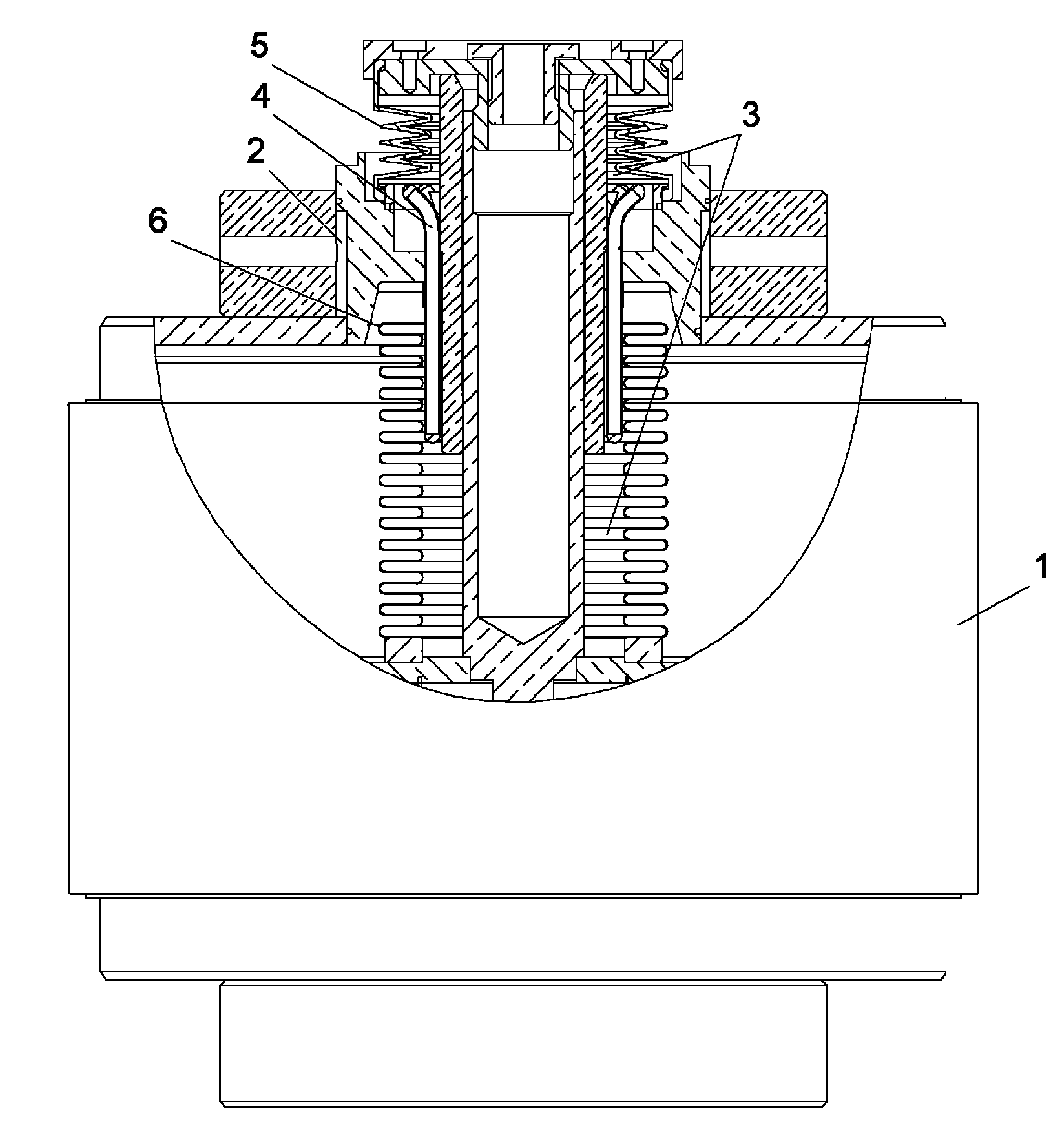
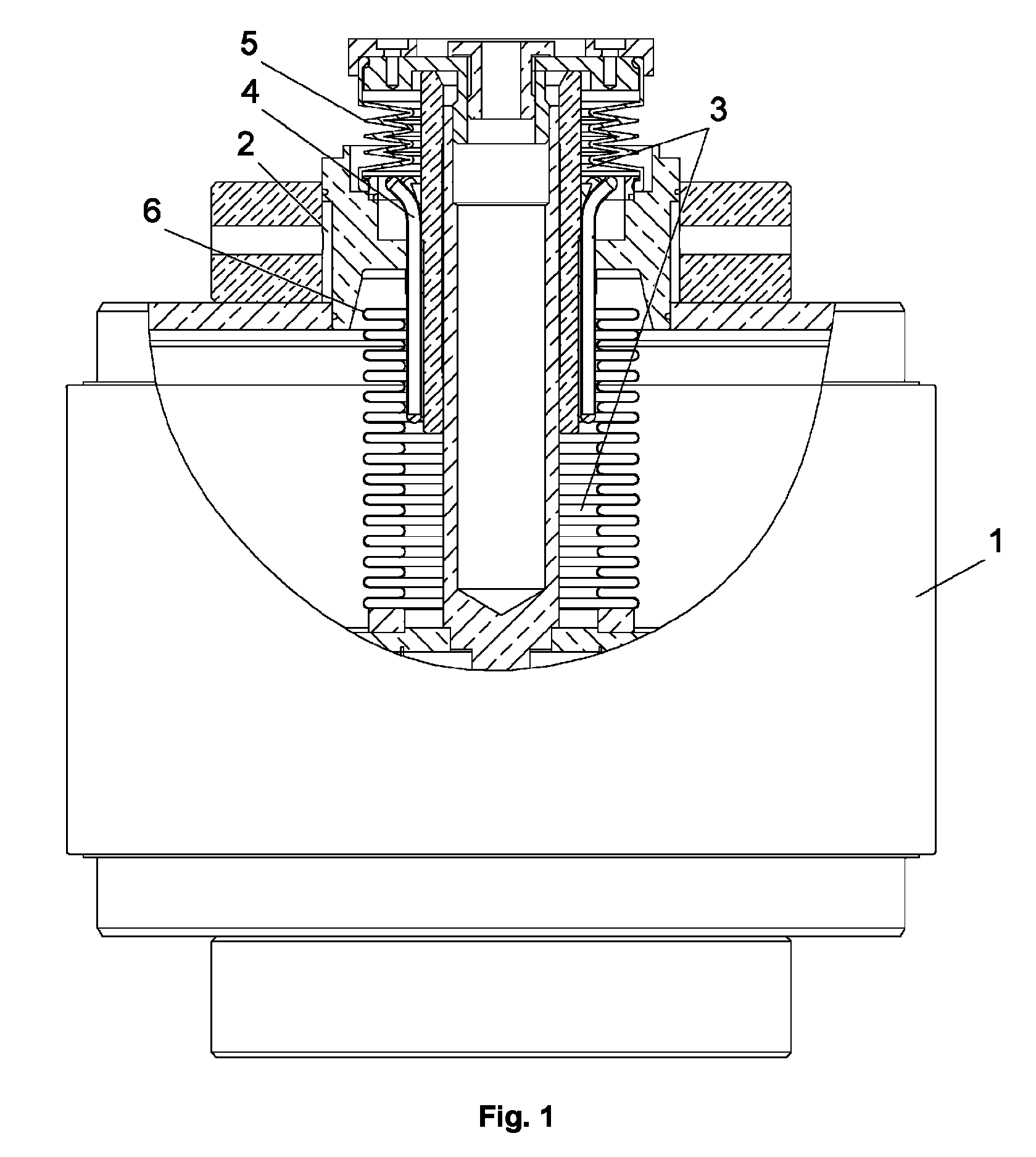
[0015]In FIG. 1, the reference numeral 1 refers to a variable vacuum capacitor. In particular, the variable vacuum capacitor comprises two electrodes which are electrically separated by means of an insulator and which are arranged inside a vacuum. In FIG. 1, the electrodes are not shown. In FIG. 1, a cooling system for a variable vacuum capacitor 1 is shown. In FIG. 1, the reference numeral 2 refers to a cooling circuit. The cooling circuit 2 is arranged outside the variable vacuum capacitor 1. The cooling circuit 2 may be a high pressure cooling circuit. The cooling circuit 2 may be designed to transport heat energy away from the outside of the variable vacuum capacitor. The transport of heat energy may be enforced by means of a suitable transportation of water. However, any other means for transporting heat energy away from the outside of the variable vacuum capacitor may be used. Such other means may comprise, for example, several laminations arranged on the surface of the variab...


PUM


Abstract

In a cooling system for a variable vacuum capacitor, a liquid is arranged inside a cooling reservoir, a first part of the reservoir is designed to absorb heat energy from first bellows of the variable vacuum capacitor, the first bellows being responsible for transporting electrical energy to a second electrode of the variable vacuum capacitor, a second part of the reservoir is designed to dissipate heat energy towards a cooling circuit, and heat pipes are arranged between the first part of the reservoir and the second part of the reservoir.

Description

BACKGROUND AND SUMMARY[0001]The present invention relates to a cooling system for a variable vacuum capacitor.[0002]In the prior art, for various purposes, fixed vacuum capacitors with a certain capacitance and variable vacuum capacitors with a capacitance that is adjustable within a certain range are used. Vacuum capacitors may be used in broadcast systems, in systems for the production of flat panel displays or semiconductors, or in other industrial applications. Vacuum as a dielectric medium offers many advantages. Because of the high dielectric strength, it is possible to maintain very close plate spacing and still have a capacitor with good high voltage capabilities. Should a breakdown occur in a vacuum capacitor, this does not normally result in permanent damage which is often the case with capacitors with other dielectrics, such as paper, SF6, or other dielectrics. Variable vacuum capacitors often comprise a first electrode that, by means of a metal bellows, is movably arrang...

Claims


Application Information

Patent Timeline
Patent Type & Authority Patents(United States)
IPC IPC(8): H05K7/20H01G5/00
CPCH01G5/01H01G5/017
Inventor JAGGI, MANUELBIGLER, WALTER
Owner COMET HOLDING
Why Eureka
Try Eureka