Tubular vascular transplant

Inactive Publication Date: 2012-03-27
HEISE MICHAEL +1
View PDF5 Cites 40 Cited by
  • Summary
  • Abstract
  • Description
  • Claims
  • Application Information

AI Technical Summary

Benefits of technology

[0022]The blood flow speed can be cut off in a controlled manner and reduced by placing a diffuser into the distal area of the transplant when using an arteriovenous shunt in the venous part region of this shunt. Significantly reduced wall shear stress (WSS) of the receiving vessels (i.e.: a vein) can be achieved by slowing down the flow. The cone angle should be selected at less than 10°, preferably between 6° and 7°. Otherwise flow separation will reoccur and pseudointima will develop.
[0023]By placing a diffuser in the distal region of the transplant, the formation of an intimal hyperplasi

Problems solved by technology

A general problem with such tubular vascular transplants is the formation of a stenosis in the distal region of the transplant.
Similar problems also arise with peripheral transplants

Method used


Image

  • Tubular vascular transplant
  • Tubular vascular transplant
  • Tubular vascular transplant

Examples


Embodiment Construction

[0039]The preferred embodiments of the present invention will now be described with reference to FIGS. 1-8 of the drawings. Identical elements in the two figures are designated with the same reference numerals.

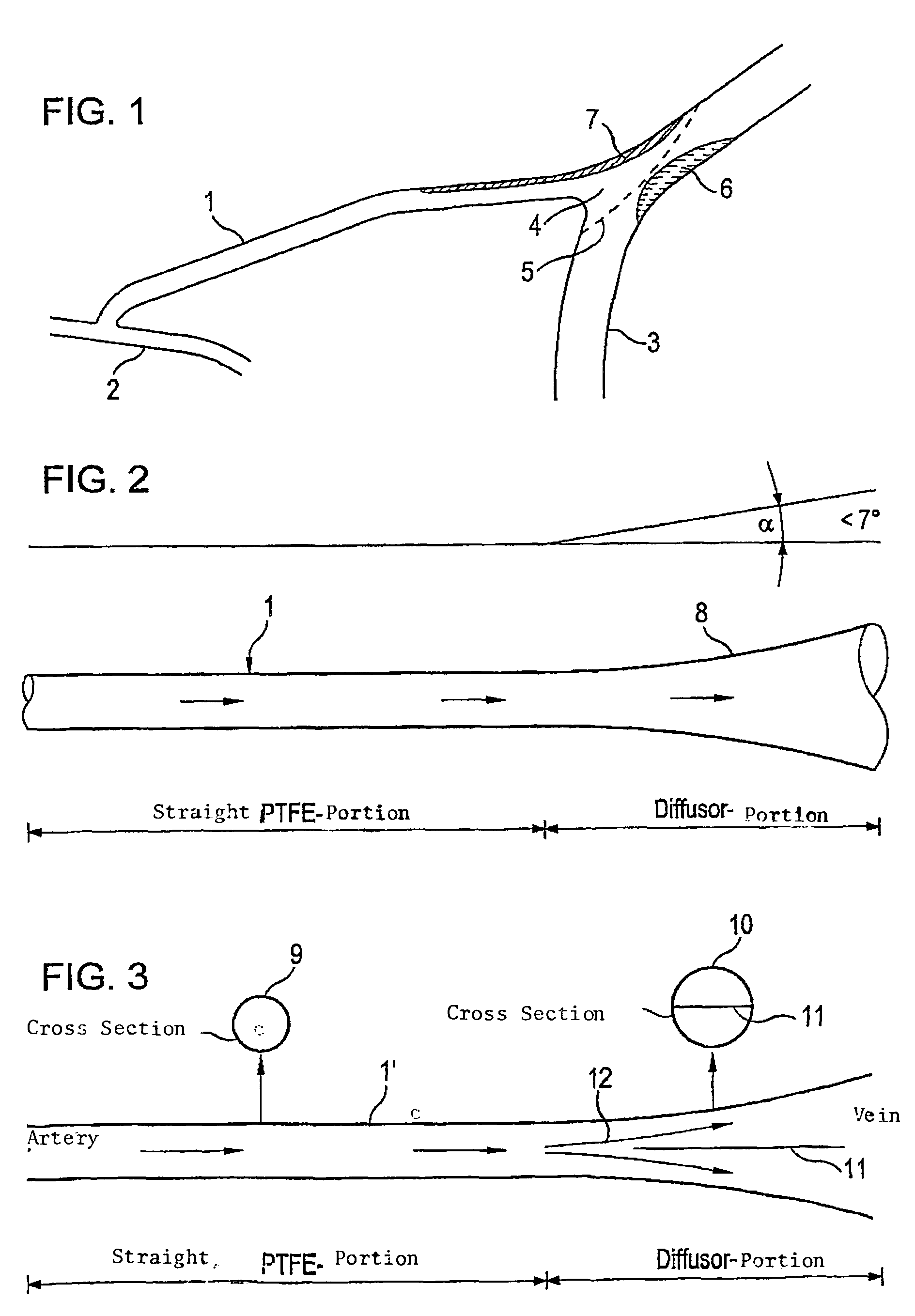
[0040]FIG. 1 shows an arteriovenous shunt that connects an artery 2 with a vein 3. Shunt 1 is a tubular vascular transplant made of ePTFE that diverts at its proximal end of the artery 2 and leads into vein 3 with primarily the same diameter whereby the connection between shunt 1 and the vein occurs via a flange 4. This is connected with vein 3 by a dash line suture 5. As explained previously, an intimal hyperplasia 6 is formed via an angular penetrated central blood flow at the base body of the vein which is released due to the high wall shear stress (WSS). Parallel to this pseudointimal hyperplasia 7 is formed in shunt 1 in the distal region which is primarily released by separation zones in the blood flow.

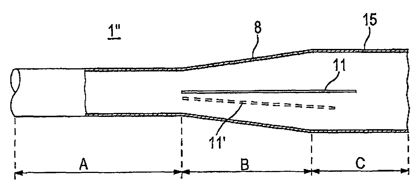
[0041]FIG. 2 shows a schematic part of an arteriovenous shunt 1 accor...


PUM


Abstract

A tubular vascular transplant (1, 1′, 1″, 1′″) serves for connecting vessels in the human body. The transplant, in particular made of expanded polytetrafluoroethylene (ePTFE), can preferably be used for an arteriovenous shunt for carrying out a dialysis. The transplant is connected by its first, proximal end to a vessel, for example an artery (2), and by its distal end to another location of the same vessel or to a different vessel, for example a vein (3). The lumen of the transplant (1, 1′, 1″, and 1′″) widens in a steadily conical manner in the region of its distal end and forms a diffuser (8) there. The cone angle (a) of the wall of the diffuser (8) with respect to the central flow direction of the blood in the transplant (1′, 1″, 1′″) is preferably 6° to 7°. In the region of the diffuser (8), preferably at least one, preferably planar, dividing wall (11, 11′, 11a, and 11b) is provided, running in the central flow direction of the blood. This makes it possible to prevent the formation of an intimal hyperplasia and a pseudointima.

Description

BACKGROUND OF THE INVENTION[0001]The invention refers to a tubular vascular transplant.[0002]Such transplants are used to connect perfused blood vessels in the human body. The transplant is connected by its first proximal end to a vessel and by its second distal end to another location of the same vessel or a different vessel.[0003]An example is the so called peripheral transplant which is used to bypass a non-perfused blood vessel with the aid of the transplant. Applications within an end-to-side-anastomosis are possible.[0004]Another example of this type of tubular vascular transplant is an arteriovenous shunt. It is a parallel or bypass connection between an artery and a vein, usually in the upper or lower arm to enable operative vascular access during a dialysis. This type of shunt is used when the patient's own veins are inadequately developed to allow for an effective dialysis. Using an arteriovenous shunt, flow rates of up to 1000 milliliters per minute (1000 ml / min) are poss...

Claims


Application Information

Patent Timeline
IPC IPC(8): A61M5/00A61F2/06
CPCA61F2/06A61F2/064A61M1/3655A61F2002/068
Inventor HEISE, MICHAELHEIDENHAIN, CHRISTOPH
Owner HEISE MICHAEL
Why Eureka
Try Eureka