Magnetic head, head assembly and magnetic recording/reproducing apparatus

a head assembly and magnetic recording technology, applied in the direction of maintaining the head carrier alignment, special recording techniques, instruments, etc., can solve the problems of increasing the size of the apparatus, affecting write signals and read signals, damage to the magnetic head, etc., and achieve the effect of effective detection of thermal asperity

Inactive Publication Date: 2012-03-27
TDK CORPARATION
View PDF15 Cites 1 Cited by
  • Summary
  • Abstract
  • Description
  • Claims
  • Application Information

AI Technical Summary

Benefits of technology

[0007]It is an object of the present invention to provide a compact magnetic head, a head assembly, and a magnetic recording / reproducing apparatus which are capable of effectively detecting thermal asperity.
[0011]With this magnetic head, since the resistive element is disposed closer to the air bearing surface, which is to be opposed to a magnetic medium, than the recording coil, thermal asperity can be instantaneously and accurately detected at a position close to a position where collision against a ridge of the magnetic medium will occur. In addition, since the reproducing element is not used for detection, it has not only high reliability but also broad options for the material because there is no limit to the temperature coefficient of the resistive element.
[0012]Moreover, since the resistive element is connected in series or in parallel with the heat-generating resistor, power can be fed through a common wiring, which eliminates the waste of wiring and achieves miniaturization.

Problems solved by technology

However, there is a problem that such a decrease in the flying height causes the phenomenon of generating frictional heat due to collision of the magnetic head against a ridge on the surface of a magnetic disk, so-called thermal asperity (hereinafter referred to as TA).
Occurrence of TA not only damages the magnetic head by collision but also adversely affects write signals and read signals because the resistance of a magneto-resistive effect element momentarily changes along with an increase in temperature due to frictional heat.
However, since this technology is based on the premise that a TA detection circuit is disposed outside the magnetic head, the apparatus increases in size, which is not desirable from the viewpoint of miniaturization.
However, when using a recently prevailing TMR (tunnel magneto-resistance) element, there is a problem that since it has a low temperature coefficient, the change in resistance due to heat is too small to obtain desired detection sensitivity.
With this technology, moreover, the reproducing element collides against a ridge of the magnetic disk, which is not desirable from the viewpoint of reliability.
However, this has a problem that there is a limit to selection of temperature coefficient.

Method used


Image

  • Magnetic head, head assembly and magnetic recording/reproducing apparatus
  • Magnetic head, head assembly and magnetic recording/reproducing apparatus
  • Magnetic head, head assembly and magnetic recording/reproducing apparatus

Examples


Embodiment Construction

[0031]First will be described a magnetic head according to the present invention, then will be described a head assembly according to the present invention, and finally will be described a magnetic recording / reproducing apparatus according to the present invention.

1. Magnetic Head

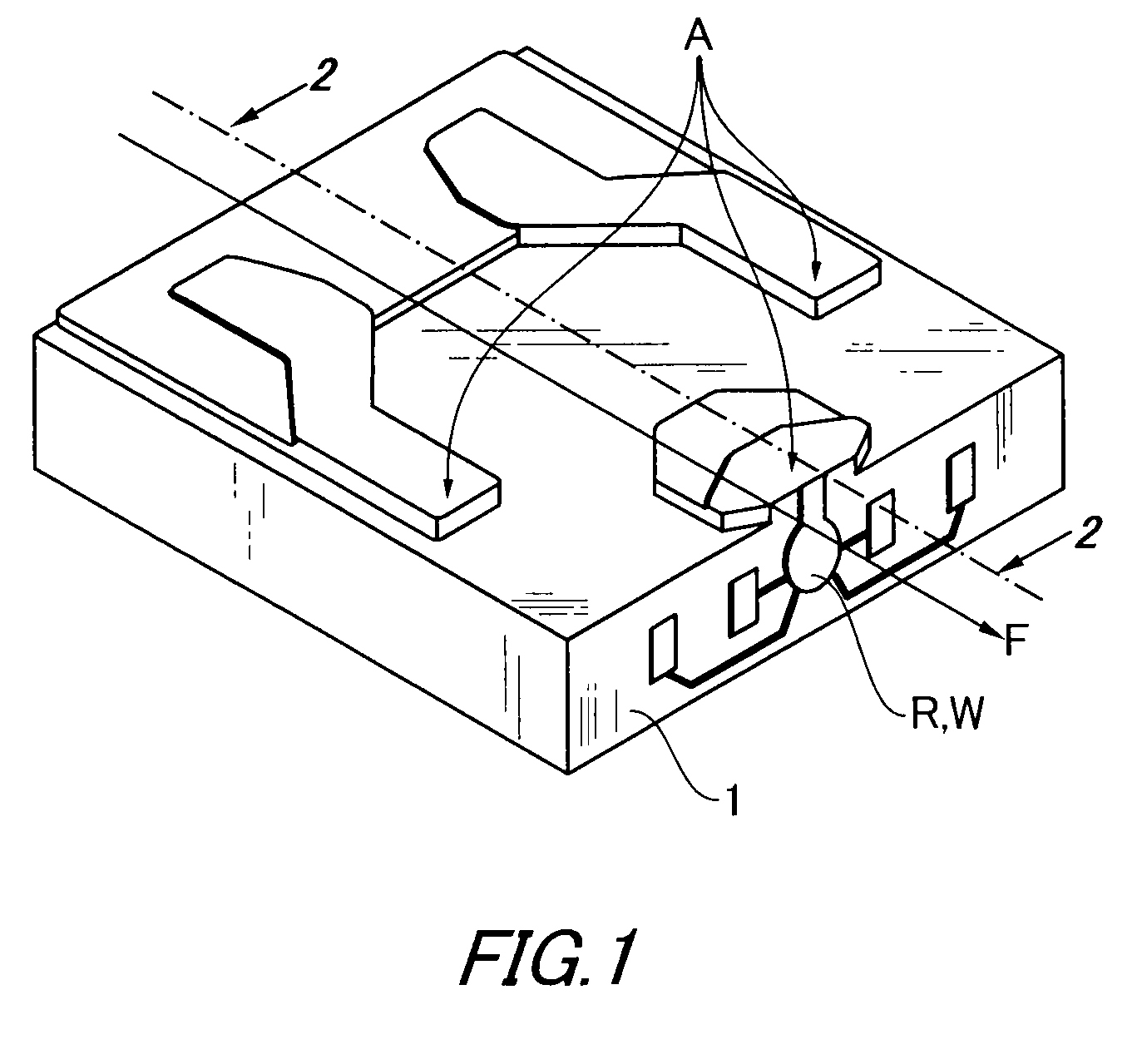
[0032]FIG. 1 shows a magnetic head to be used in combination with a rapidly spinning magnetic recording medium such as a hard disk. Magnetic heads of this type are generally called flying-type.

[0033]Referring first to FIG. 1, the magnetic head has a slider substrate 1 of a generally rectangular parallelepiped structure. The slider substrate 1 has an air bearing surface A directly relating to the flying characteristics and a recording / reproducing head (R,W) on a lateral end face located at the side of an air flow-out end with respect to an air flow direction F.

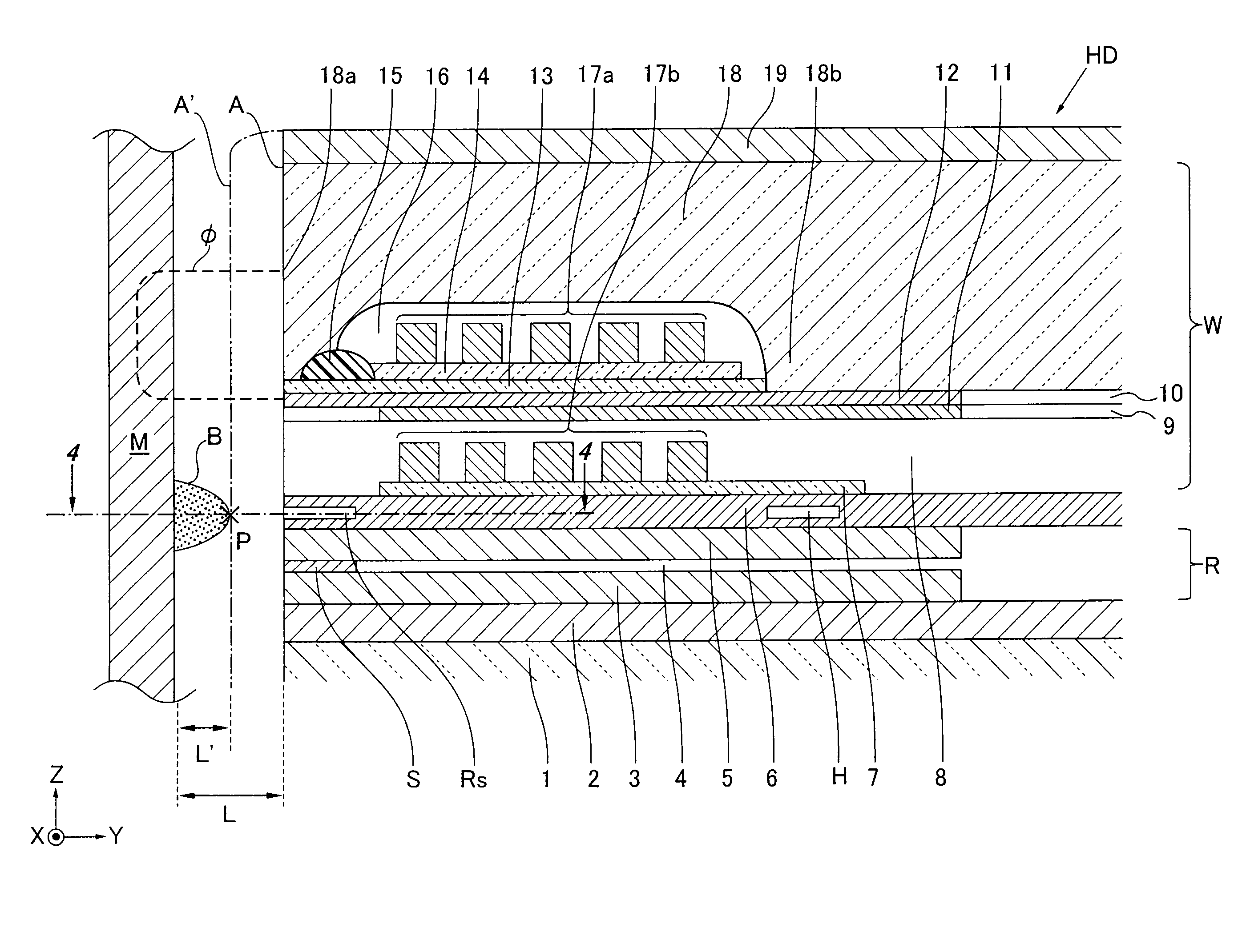
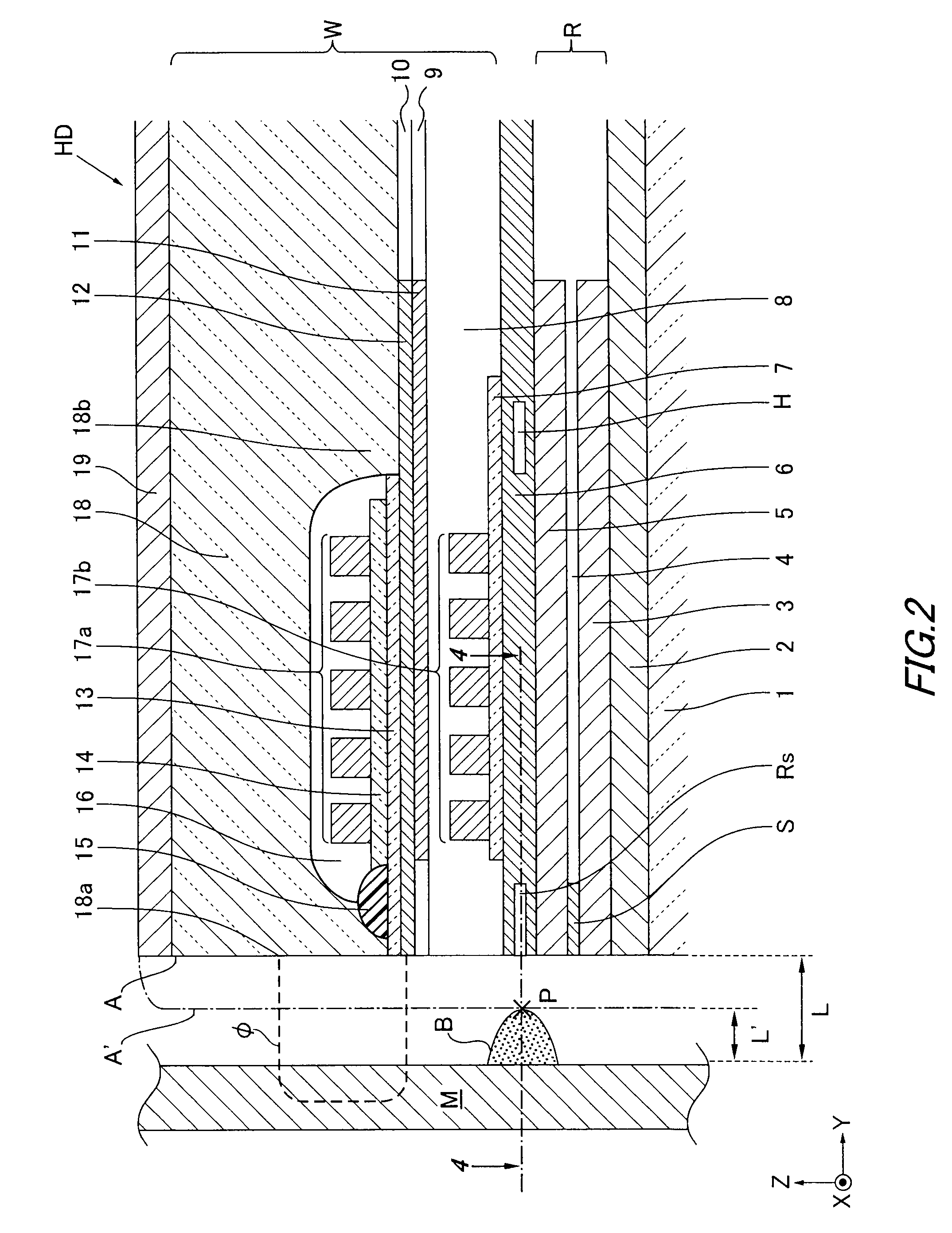
[0034]Details of the recording / reproducing head (R,W) are shown in FIG. 2. FIG. 2 is a section taken along line 2-2 in FIG. 1. It should be noted that...


PUM

PropertyMeasurementUnit
distanceaaaaaaaaaa
widthaaaaaaaaaa
magnetic fieldaaaaaaaaaa

Abstract

The present invention relates to a magnetic head, a head assembly, and a magnetic recording / reproducing apparatus which are capable of effectively detecting thermal asperity. The magnetic head according to the present invention includes a heat-generating resistor, a recording coil, and a resistive element. The heat-generating resistor is adapted to generate heat when power is fed thereto so that the heat generation causes at least a part of the air bearing surface to thermally expand and protrude. The recording coil is adapted to generate a recording magnetic field, and the resistive element is disposed closer to the air bearing surface than the recording coil and connected in series or in parallel with the heater. Thus, the resistive element can share a common wiring with the heater for power feeding, which eliminates the waste of wiring and achieves miniaturization.

Description

TECHNICAL FIELD[0001]The present invention relates to a magnetic head, a head assembly, and a magnetic recording / reproducing apparatus.BACKGROUND OF THE INVENTION[0002]In the field of magnetic heads to be mounted on a magnetic recording / reproducing apparatus such as a hard disk drive (HDD), recently, the flying height of a magnetic head to be mounted has been dramatically decreased along with improvement in recording density, falling below 10 (nm). However, there is a problem that such a decrease in the flying height causes the phenomenon of generating frictional heat due to collision of the magnetic head against a ridge on the surface of a magnetic disk, so-called thermal asperity (hereinafter referred to as TA).[0003]Occurrence of TA not only damages the magnetic head by collision but also adversely affects write signals and read signals because the resistance of a magneto-resistive effect element momentarily changes along with an increase in temperature due to frictional heat.[00...

Claims


Application Information

Patent Timeline
Patent Type & Authority Patents(United States)
IPC IPC(8): G11B5/10G11B5/56
CPCG11B5/314G11B5/6064G11B2005/0005G11B5/607G11B5/6076
Inventor ANTOKU, YOSUKEKAGAMI, TAKEOKURIHARA, KATSUKIOIKE, TAROSANO, MASASHI
Owner TDK CORPARATION
Why Eureka
Try Eureka