Turbine engine wheel

a technology of turbine engine and engine body, which is applied in the direction of liquid fuel engine, marine propulsion, vessel construction, etc., can solve the problems of increasing the mass of the disk, difficult sizing of parts, and increasing the risk of poor quality, and achieves the effect of simple, economical and effectiv

Active Publication Date: 2012-04-03
SN DETUDE & DE CONSTR DE MOTEURS DAVIATION S N E C M A
View PDF9 Cites 3 Cited by
  • Summary
  • Abstract
  • Description
  • Claims
  • Application Information

AI Technical Summary

Benefits of technology

[0008]The invention is intended in particular to provide a simple, economical and effective solution to these problems, enabling the disadvantages of the prior art to be overcome.

Problems solved by technology

This large sizing increases the mass of the disk.
The axial holding of the rings of metal matrix composite (MMC) material traditionally requires drilling the disk for the passage of screws or bolts, which drilling is a source of overstress generally making the sizing of the parts tricky, or requires machining of the ring that is difficult to perform and that increases the risks of poor quality.

Method used


Image

  • Turbine engine wheel
  • Turbine engine wheel
  • Turbine engine wheel

Examples


Embodiment Construction

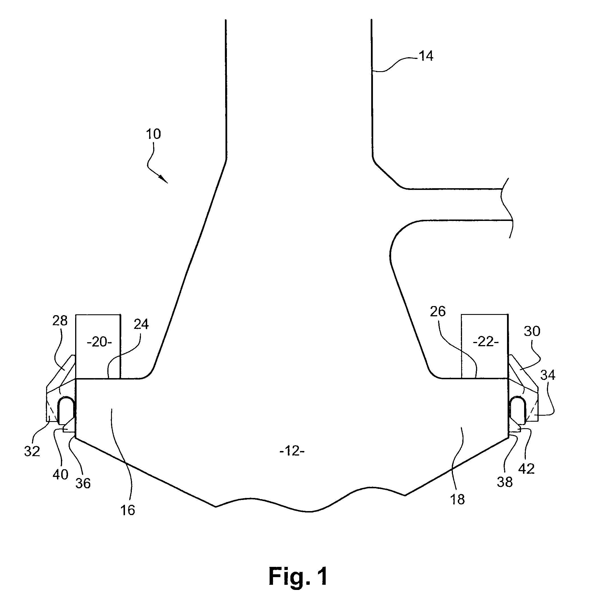
[0038]FIG. 1 shows a turbine engine wheel 10, such as a compressor or turbine, or a centrifugal impeller wheel. This wheel 10 includes a disk 12, which is traditionally made of an alloy of titanium or nickel or any appropriate material, and which has, at its periphery, blades 14 that, in the example shown, are machined directly in the disk 12, but that can also be attached to the disk by “broach”, “hammer” or “fir tree fitting” attachments, for example, without going beyond the scope of the invention.

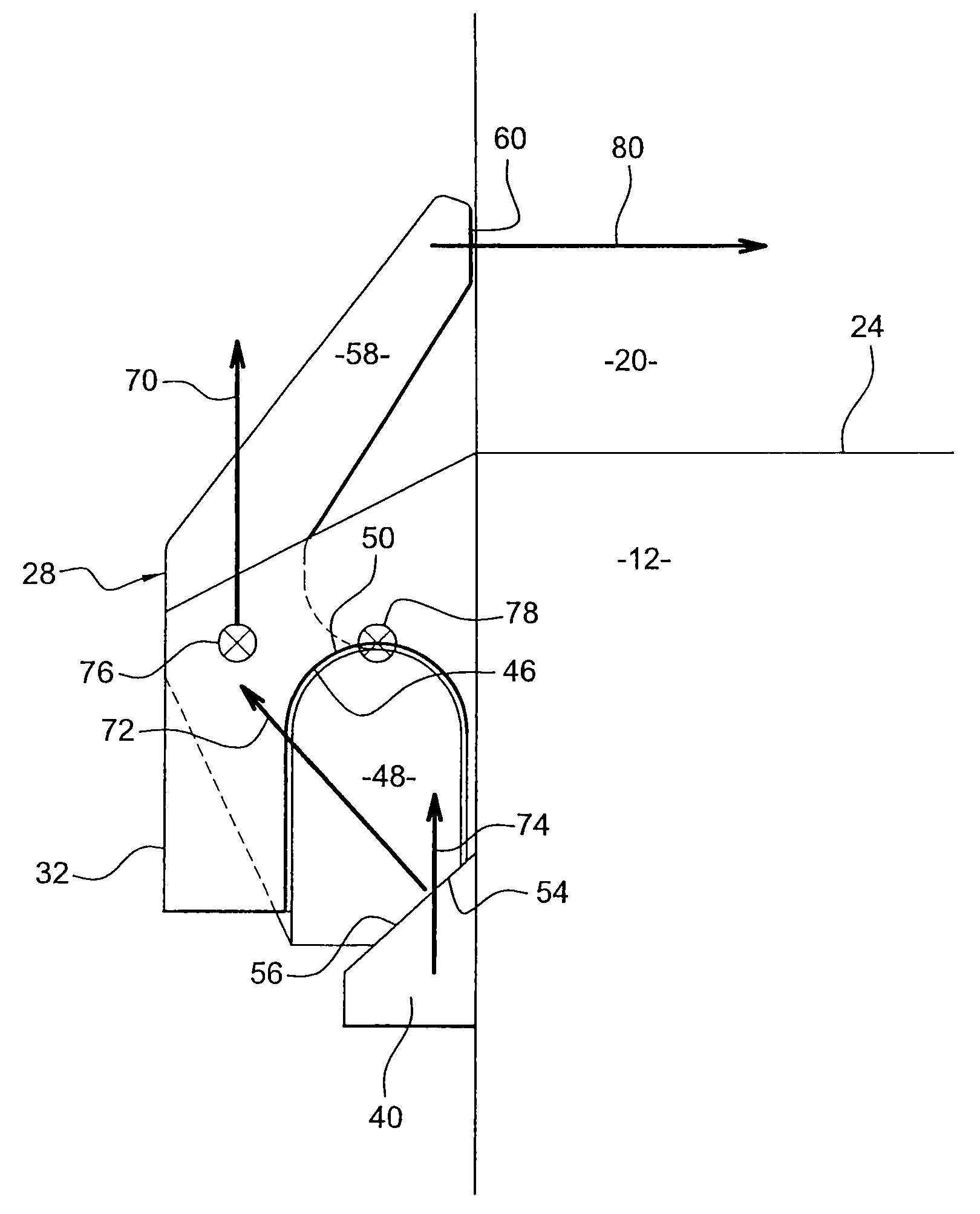
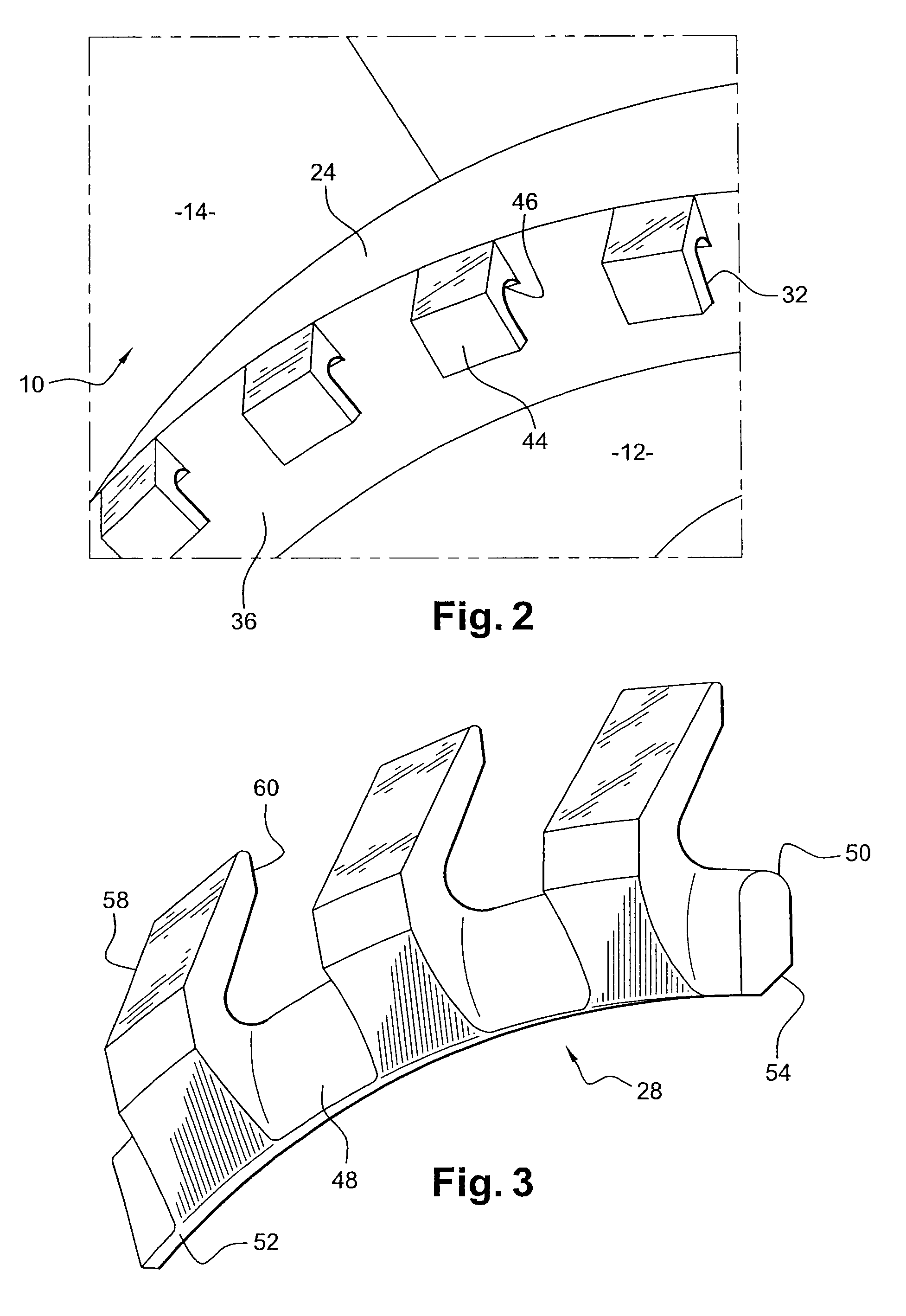
[0039]The disk 12 includes an upstream annular edge 16 and a downstream annular edge 18, which are surrounded by rings of metal matrix composite (MMC) material, respectively upstream 20 and downstream 22, intended to take up the centrifugal forces generated by the blades 14 when the disk is rotating.

[0040]These rings 20, 22 are, for example, made of silicon carbide fibers in a titanium-based matrix, but they can also be made with other types of fibers, such as boron or alumina carbide f...


PUM


Abstract

A wheel of a turbine engine such as an airplane turbojet is disclosed. The wheel includes a disk having blades and at least one ring of a metal matrix composite material mounted on the disk in order to take up centrifugal forces during operation. The wheel further includes at least one annular flange formed by sections arranged end-to-end and each including a radially internal annular portion applied on a flank of the disk and a radially external portion coming into contact with the ring in order to ensure the axial holding of the latter on the disk, and a device for radially holding flange sections on the disk.

Description

BACKGROUND OF THE INVENTION[0001]1. Field of the Invention[0002]The present invention relates to a turbine engine wheel, such as an airplane turbine engine, and more specifically to the attachment of centrifugal force take-up rings on such a wheel.[0003]2. Description of the Related Art[0004]Each wheel of a turbine engine includes a series of blades attached to or formed on a rotor disk that is secured to a rotating shaft. In operation, the blades exert, on the rotor disk, very high centrifugal forces, making it necessary to size the disk so that it can withstand forces with a certain margin of safety. This large sizing increases the mass of the disk.[0005]To overcome this disadvantage, it is known to use rings made of a metal matrix composite (MMC) material, which are mounted on the rotor disks so as to withstand the centrifugal forces exerted during operation by the blades on the disks, enabling the disks to be lightened.[0006]These rings have the special feature of being both lig...

Claims


Application Information

Patent Timeline
Patent Type & Authority Patents(United States)
IPC IPC(8): B63H1/08F01D5/22
CPCF01D5/02F01D5/3007F01D21/04F05D2300/603Y02T50/672F05D2260/30Y02T50/60
Inventor FABRE, ADRIEN JACQUES PHILIPPE
Owner SN DETUDE & DE CONSTR DE MOTEURS DAVIATION S N E C M A
Why Eureka
Try Eureka