Power unit for motorcycle

a technology for power units and motorcycles, applied in machines/engines, transportation and packaging, gearing, etc., can solve the problems of more complex configuration of oil passages, and achieve the effect of reducing the number of necessary oil passages, simple structure of oil passages, and preventing the charge of starter systems when internal combustion engines are started

Inactive Publication Date: 2012-04-03
HONDA MOTOR CO LTD
View PDF13 Cites 8 Cited by
  • Summary
  • Abstract
  • Description
  • Claims
  • Application Information

AI Technical Summary

Benefits of technology

[0015]According to the embodiments of the present invention, the input clutch, which is set between the crankshaft and the drive pulley shaft, is provided on the drive pulley shaft while the starter clutch, which is set between the driven pulley shaft and a rear wheel, is provided on the driven pulley shaft. Consequently, when the internal combustion engine is started, the transmission of power to the continuously variable transmission side can be discontinued. As a result, the load charged on the starter system when the internal combustion engine is started can be reduced. Thus, the starter system can be made more compact in dimension. In addition, even with a disconnection of the starter clutch that occurs when the internal combustion engine is stopped, the torque from the crankshaft can be transmitted to the continuously variable transmission via the input clutch. Thus, the continuously variable transmission can be shifted from a higher-speed state to a lower-speed state. Consequently, the continuously variable transmission is prevented from remaining in a higher-speed state at the next occasion of starting the motorcycle. Moreover, the switching between the engagement and the disengagement of one of the input clutch and the starter clutch is hydraulically controlled while the switching between the engagement and the disengagement of the other one of the input clutch and the starter clutch is mechanically controlled. Consequently, the number of necessary oil passages is prevented from becoming large, and a simple structure of the oil passages can be accomplished. Thus, the formation of oil passages no longer needs special consideration.
[0016]According to an embodiment of the invention, in particular, more flexibility in design can be accomplished. When all the clutches are hydraulically controlled, less flexibility is allowed in designing the arrangement of the clutches. The arrangement of the mechanically-switchable clutch outside the transmission chamber allows a more flexible design. The arrangement of one of the input clutch and the starter clutch outside the transmission chamber allows the transmission chamber to be made more compact in dimension. The clutch, disposed outside the transmission chamber, can be designed so as to have a larger diameter and to be more compact in dimension in the axial direction without affecting the dimension of the transmission chamber. In addition, the diameter of the clutch disposed outside the transmission chamber can be made not to be limited by the pulley shafts inside the transmission chamber. Consequently, the diameter of the clutch can be selected more flexibly, so that the clutch can be made more compact in the axial direction. The compact clutch, together with the compact transmission chamber, can contribute to the accomplishment of a more compact power unit.
[0017]According to an embodiment of the invention, in particular, the clutch which is housed in the transmission chamber, and which is provided on a first one of the drive and the driven pulley shafts is disposed at the opposite side of the continuously variable transmission from the hydraulic drive mechanism annexed to a pulley provided on a second one of the drive pulley shaft and of the driven pulley shafts. Consequently, the clutch housed in the transmission chamber, can have as large a diameter as to get close to the second one of the drive and the driven pulley shafts. Thus, the diameter of the clutch can be selected more flexible.
[0018]According to an embodiment of the invention, in particular, the input clutch and the starter clutch are arranged so as to partially overlap each other when viewed in the axial direction. Consequently, the two clutches can have larger diameters, and can be made more compact in the axial direction. Moreover, the distance between the drive pulley shaft and the driven pulley shaft can be made narrower, so that the power unit can be made more compact.
[0019]According to an embodiment of the invention, in particular, the input clutch is linked and interlocked with the side stand. Consequently, the power transmission from the crankshaft to the continuously variable transmission is prevented from occurring while the side stand is in use.

Problems solved by technology

The larger the number of oil passages becomes, the more complex the configuration of oil passages becomes.

Method used


Image

  • Power unit for motorcycle
  • Power unit for motorcycle
  • Power unit for motorcycle

Examples


first embodiment

[0083]Now, descriptions will be given as to some advantageous effects of the The input clutch is provided on the drive pulley shaft 40 as being set between the crankshaft 12 and the drive pulley shaft 40 while the starter clutch 38 is provided on the driven pulley shaft 41 as being set between the driven pulley shaft 41 and the rear wheel. Consequently, when the internal combustion engine EA starts, the power transmission to the continuously-variable-transmission 36 side can be discontinued. The load on the starter system at the time of starting the internal combustion engine EA can be reduced, and thus the starter system can be made smaller in dimension. In addition, even with a disconnection of the starter clutch 38 that occurs at the time of stopping the internal combustion engine EA, the torque from the crankshaft 12 can be transmitted to the continuously variable transmission 36 via the input clutch 51. Thus, the continuously variable transmission 36 can be shifted from a high...

second embodiment

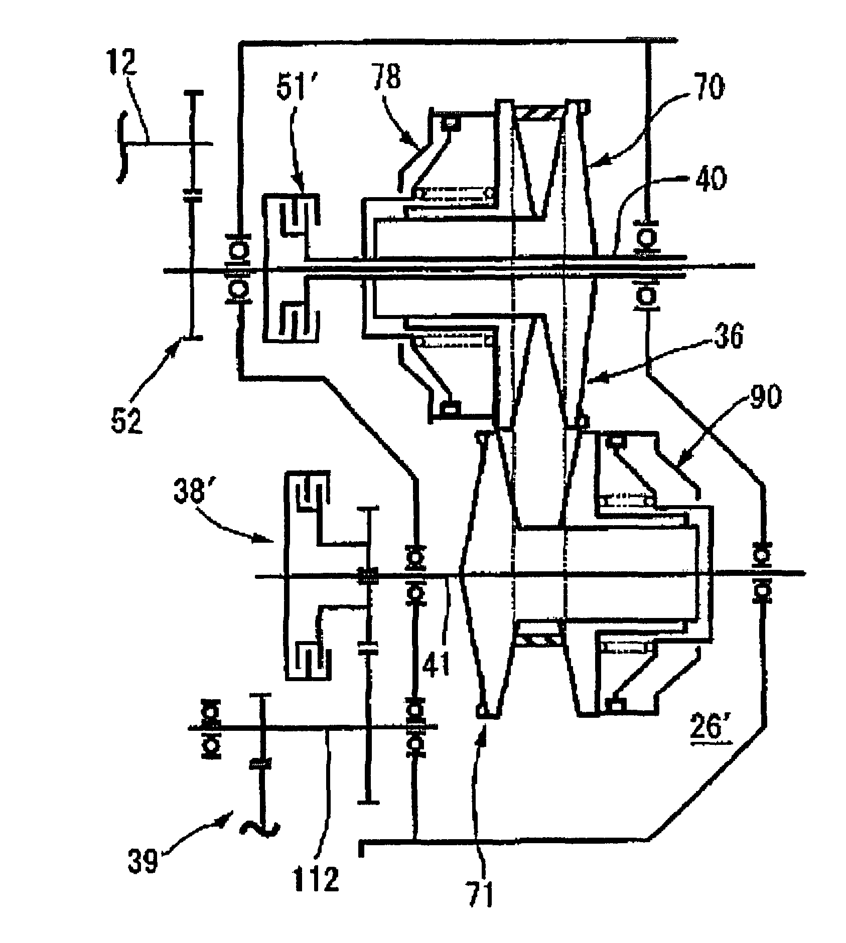
[0090]FIG. 8 shows the present invention. An input clutch 51′ switches between the connection of and the disconnection of the transmission of drive power from the crankshaft 12 to the drive pulley shaft 40 via the primary reduction-gear mechanism 52. The switching between the engagement and the disengagement of the input clutch 51′ is controlled hydraulically, and the input clutch 51′ is housed in a transmission chamber 26′. A starter clutch 38′, on the other hand, is provided on the driven pulley shaft 41 and is set between the driven pulley 41 and the rear wheel. The switching between the engagement and the disengagement of the starter clutch 38′ is controlled mechanically, and the starter clutch 38′ is housed outside of the transmission chamber 26′.

[0091]In addition, the input clutch 51′ is housed in the transmission chamber 26′ and is provided on the drive pulley shaft 40, while the driven-side hydraulic drive mechanism 90 is annexed to the driven pulley 71 provided on the drive...

third embodiment

[0093]FIGS. 9 and 10 show the present invention.

[0094]Note that the component parts that respectively correspond to those in the first and the second embodiments are given the same reference numerals as those in the first and the second embodiments, and no detail descriptions of those parts will be given here.

[0095]In FIG. 9, a head pipe 190 is provided at the front end of a body frame F of the motorcycle steerably supports the front fork 191, which pivotally supports a front wheel WF. Between the front wheel WF and a rear wheel WR, a power unit PB is mounted on the body frame F. The power unit PB is composed of, for example, a V-type four-cylinder internal combustion engine EB and of a power transmission system TB. The power transmission system TB transmits the power from the internal combustion engine EB to the drive wheel, that is, the rear wheel WR, while reducing the speed of the transmitted power.

[0096]An engine body 192 of the internal combustion engine EB includes a crankcas...


PUM


Abstract

A power unit for a motorcycle having a continuously variable transmission, which is housed in a transmission chamber inside a engine body and which accomplishes stepless changes in the transmission of power from a drive pulley shaft to a driven pulley shaft by changing the effective diameter with which a belt actually wraps around each of the drive and the driven pulleys. An input clutch is set between a crankshaft and a drive pulley and is provided on the drive pulley shaft. A starter clutch is set between a driven pulley shaft and a rear wheel and is provided on the driven pulley shaft. The switching between the engagement and disengagement of one of the input clutch and the starter clutch is hydraulically controlled. Meanwhile, the switching between the engagement and disengagement of the other one of the input clutch and the starter clutch is mechanically controlled.

Description

CROSS-REFERENCE TO RELATED APPLICATIONS[0001]The present application claims priority under 35 USC 119 to Japanese Patent Application No. 2006-356235 filed on Dec. 28, 2006 the entire contents thereof is hereby incorporated by reference.BACKGROUND OF THE INVENTION[0002]1. Field of the Invention[0003]The present invention relates to a power unit for a motorcycle. In the power unit, a continuously variable transmission is housed in a transmission chamber of an engine body. The continuously variable transmission includes a drive pulley provided on a drive pulley shaft, to which the torque is transmitted from a crankshaft, a driven pulley provided on the driven pulley shaft with its axis being parallel to the drive pulley shaft and a belt looped between the drive pulley and the driven pulley. Stepless changes in the transmission of power from the drive pulley shaft to the driven pulley shaft are accomplished by changing the effective diameter with which the belt actually wraps around eac...

Claims


Application Information

Patent Timeline
Patent Type & Authority Patents(United States)
IPC IPC(8): F16H7/02B60K17/02B60K17/06F02B61/02F02B61/06F16H9/18
CPCF16H9/18F16H57/04Y10T477/6203
Inventor NAKAJIMA, TOSHIMITSUMITSUBORI, TOSHIMASAKONDO, HITOSHI
Owner HONDA MOTOR CO LTD
Why Eureka
Try Eureka