Calibration methodology for NDIR dew point sensors

Inactive Publication Date: 2012-04-03
AIRWARE INC
View PDF9 Cites 8 Cited by
  • Summary
  • Abstract
  • Description
  • Claims
  • Application Information

AI Technical Summary

Benefits of technology

[0016]Accordingly, it is a primary object of this invention to provide NDIR

Problems solved by technology

Moisture is an important issue in many air systems, including ambient air.
Although chilled mirror technology offers the highest accuracy in dew point measurements, a dew point sensor designed around it is in essence a very delicate and precision optical instrument.
In addition, to correctly calibrate such a precision optical instrument requires not only expertly trained know-how in this technology field with years of experience but also a lot of time and effort required to be spent in doing it.
It is therefore not surprising that chilled mirror dew point sensors are extremely expensive and are only employed when absolute accuracy is essential.
While capacitive sensors provide excellent low dew point measurement accuracy to −100° C. and lower, they tend to offer poor long-term stability in processes with varying dew points at the higher ranges (e.g. refrigerant dried systems).
Metal oxide sensors can also be easily damaged by high humidity levels and condensation.
Drift in the output reading means frequent calibration which requires rather sophisticated and complex instrumentation that can only be done at the manufacturer's calibration laboratories.
Like the capacitive metal oxide sensors, calibration of capacitive polymer sensors also requires sophisticated and complex instrumentation and can only be performed at the manufacturer's laboratories prior to shipping to distributors or end-users.
It can be seen from the foregoing discussion that just about all dew point sensors available for sale today require rather elaborate and time-consumi

Method used


Image

  • Calibration methodology for NDIR dew point sensors
  • Calibration methodology for NDIR dew point sensors
  • Calibration methodology for NDIR dew point sensors

Examples


Embodiment Construction

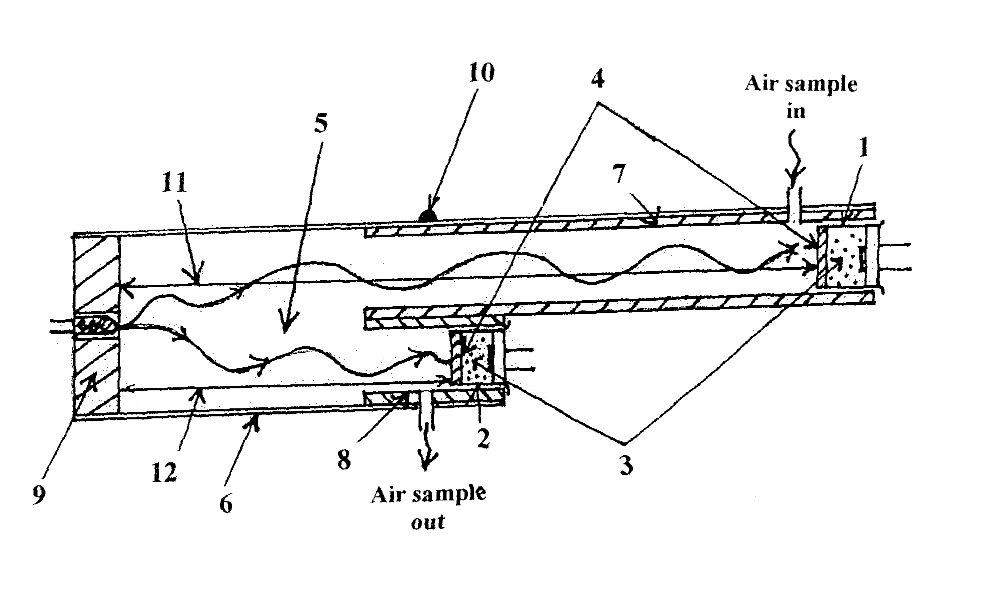
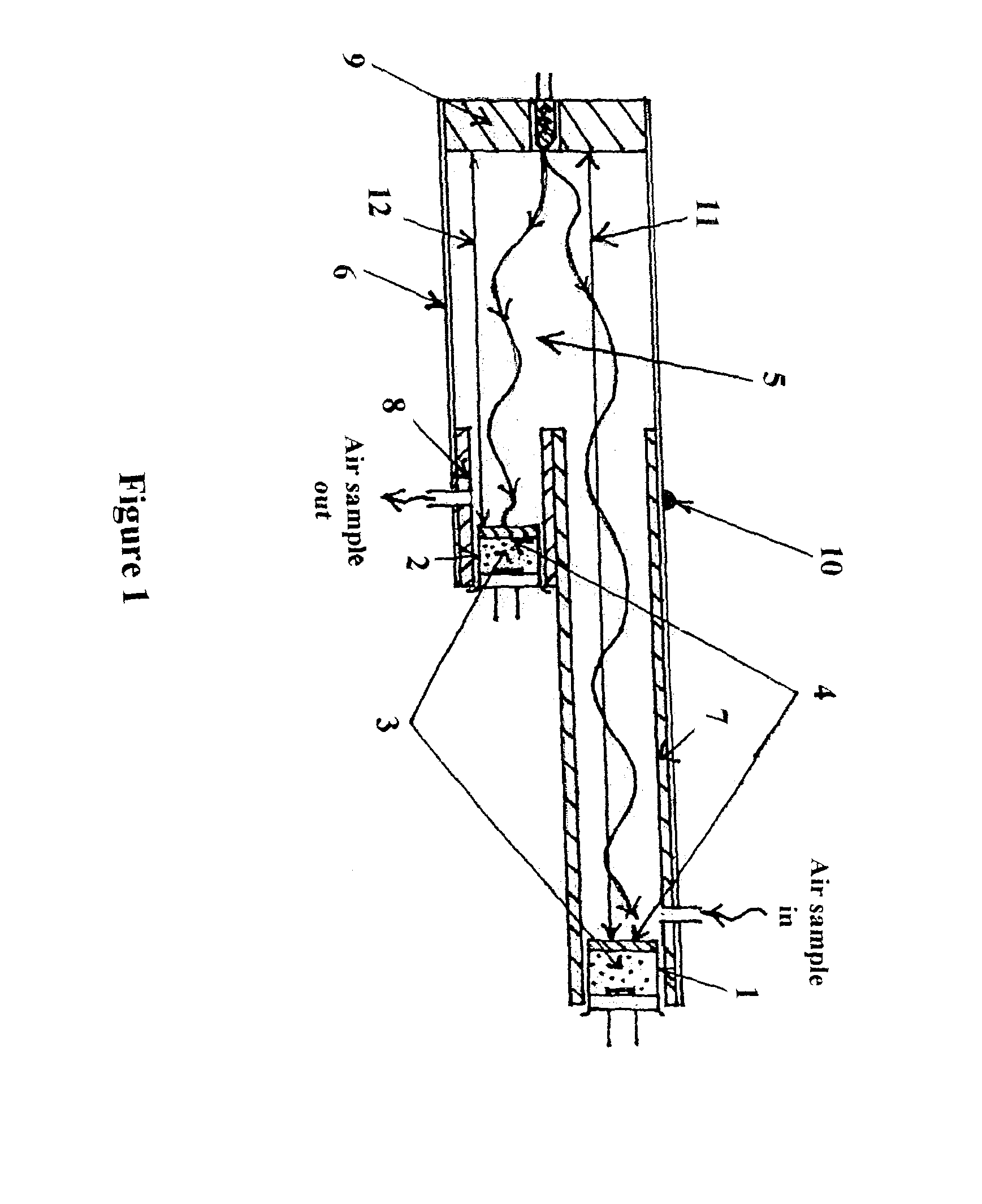
[0021]The present invention complements the teaching of advancing a methodology for NDIR gas sensors capable of significantly reducing output drifts over time disclosed in U.S. Ser. No. 12 / 859,749, the disclosure of which is specifically incorporated herein by reference. It is important to point out the fact that such a methodology only applies to NDIR gas sensors and not to other technology types of gas sensors. It is therefore appropriate to begin the detailed description of the current invention by referencing the inventor's earlier disclosed teaching in the design of a dual-beam NDIR gas sensor that is capable of significantly reducing output drifts over time. Specifically and for purposes of illustration, the dual-beam methodology discussed herein is for the implementation of an NDIR H2O or dew point gas sensor.

[0022]Prior to the teaching disclosed in U.S. Ser. No. 12 / 859,749, conventional dual-beam methodology utilized a spectral filter for the Signal channel that had its cent...


PUM


Abstract

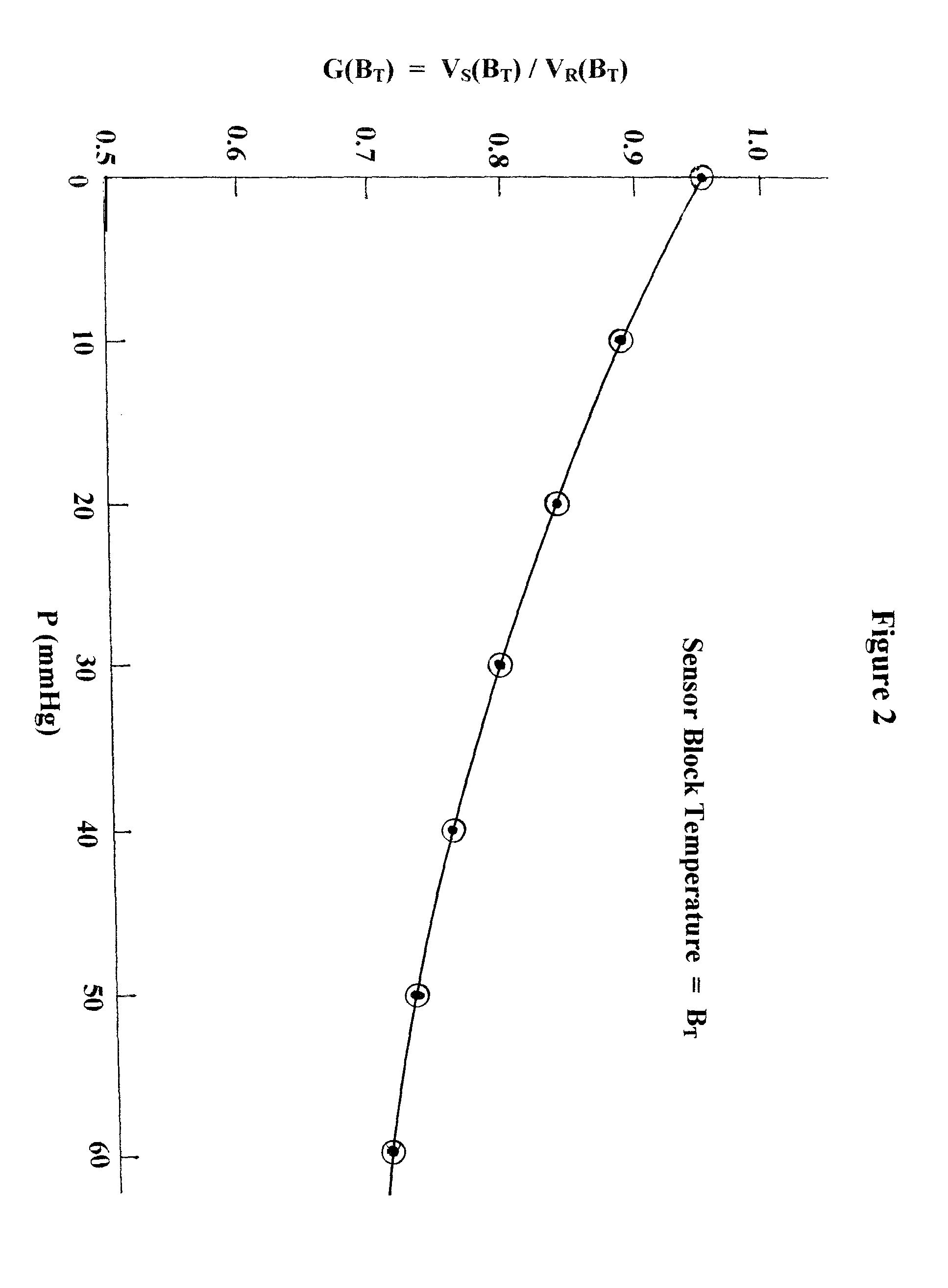
A method for calibrating a dual-beam NDIR gas sensor for detecting water vapor by obtaining a variant sensor components domain (“G0”) when there is no water vapor gas in the sample chamber, obtaining a physics measurement domain (“G”) for a set of known concentrations of the water vapor gas in the sample chamber, the known concentrations being measurable quantities exceeding zero, using G to calculate a G0i from a known concentration of water vapor in the sample chamber for each of multiple master calibration curves, and then selecting the master calibration curve with the lowest difference between its G0i and the G0 of the NDIR gas sensor as the calibration curve. G and the G0i are obtained, preferably, at substantially the same temperature, G is a signal channel output (“VS”) divided by a reference channel output (“VR”), and the master calibration curves are obtained from a set of multiple calibration curves obtained from a large number of NDIR gas sensors, each of the calibration curves being represented by an equation of P=F(G/G0) where P is equal to a gas pressure and F is a function.

Description

CROSS-REFERENCE TO RELATED APPLICATIONS[0001]This application claims priority from and is a continuation-in-part application of U.S. Ser. No. 12 / 859,749, filed Aug. 19, 2010 which claims priority from U.S. 61 / 274,874, filed Aug. 21, 2009.FIELD OF THE INVENTION[0002]The present invention is in the field of measuring instruments, and specifically relates to a method for calibrating non-dispersive infrared (NDIR) dew point sensors.BACKGROUND OF THE INVENTION[0003]Moisture is an important issue in many air systems, including ambient air. Its content in controlled air systems must be carefully measured and controlled through use of dew point sensors. The use of dew point temperature of a volume of air (expressed in ° F. or ° C.) to indicate the amount of moisture in it is based upon the operational principle of cooling a volume of air and monitoring the temperature of a surface when condensation first forms on it. The three most common types of sensors for measuring dew point today are c...

Claims


Application Information

Patent Timeline
IPC IPC(8): G01J5/02
CPCG01N21/274G01N21/3504G01N21/3554G01N33/0006G01N21/61G01N33/004
Inventor WONG, JACOB Y
Owner AIRWARE INC
Why Eureka
Try Eureka