
Thermally and acoustically insulative vehicle flooring

a technology for vehicle flooring and thermal insulation, applied in the field of vehicle flooring systems, can solve the problems of insufficient thermal insulation potential, vehicle flooring systems are often subjected to extremely high temperatures, and laminate flooring systems still have an inherent risk of delamination and failure, and achieve the effect of convenient installation, preferred thermal and acoustic performance, and cost-effectiveness

Inactive Publication Date: 2012-04-10
CVG MANAGEMENT
View PDF13 Cites 3 Cited by
  • Summary
  • Abstract
  • Description
  • Claims
  • Application Information

AI Technical Summary

Benefits of technology

"The present invention is a new and improved vehicle flooring system that overcomes the shortcomings of previous methods. It has a unique ratio of contact layer density to substrate layer density to achieve preferred thermal and acoustic performance, while still being flexible and cost-effective. The substrate layer may include a foam material, such as polyurethane foam, and may be made from recycled foam. The contact layer is bonded to the substrate layer with a water-based adhesive that withstands the temperatures of a vehicle flooring system. The thermal conductivity of the flooring system is defined in combination with a desirable ratio of contact layer density to substrate layer density for optimal comfort. The patent text describes various variations, modifications, and alternatives of the preferred embodiments."

Problems solved by technology

Over the years a number of adhesives, adhesive webs and binding fibers have been specifically developed to secure the various layers of the laminates together; however, laminated flooring systems still have an inherent risk of delamination and failure.
The potential is, in fact, significant mainly due to the harsh operating environment to which vehicle flooring systems are subjected.
As a result, the vehicle flooring systems are often subjected to extremely high temperatures, which have a tendency to degrade the adhesives and binders over time.

Method used


Image

  • Thermally and acoustically insulative vehicle flooring
  • Thermally and acoustically insulative vehicle flooring
  • Thermally and acoustically insulative vehicle flooring

Examples


Embodiment Construction

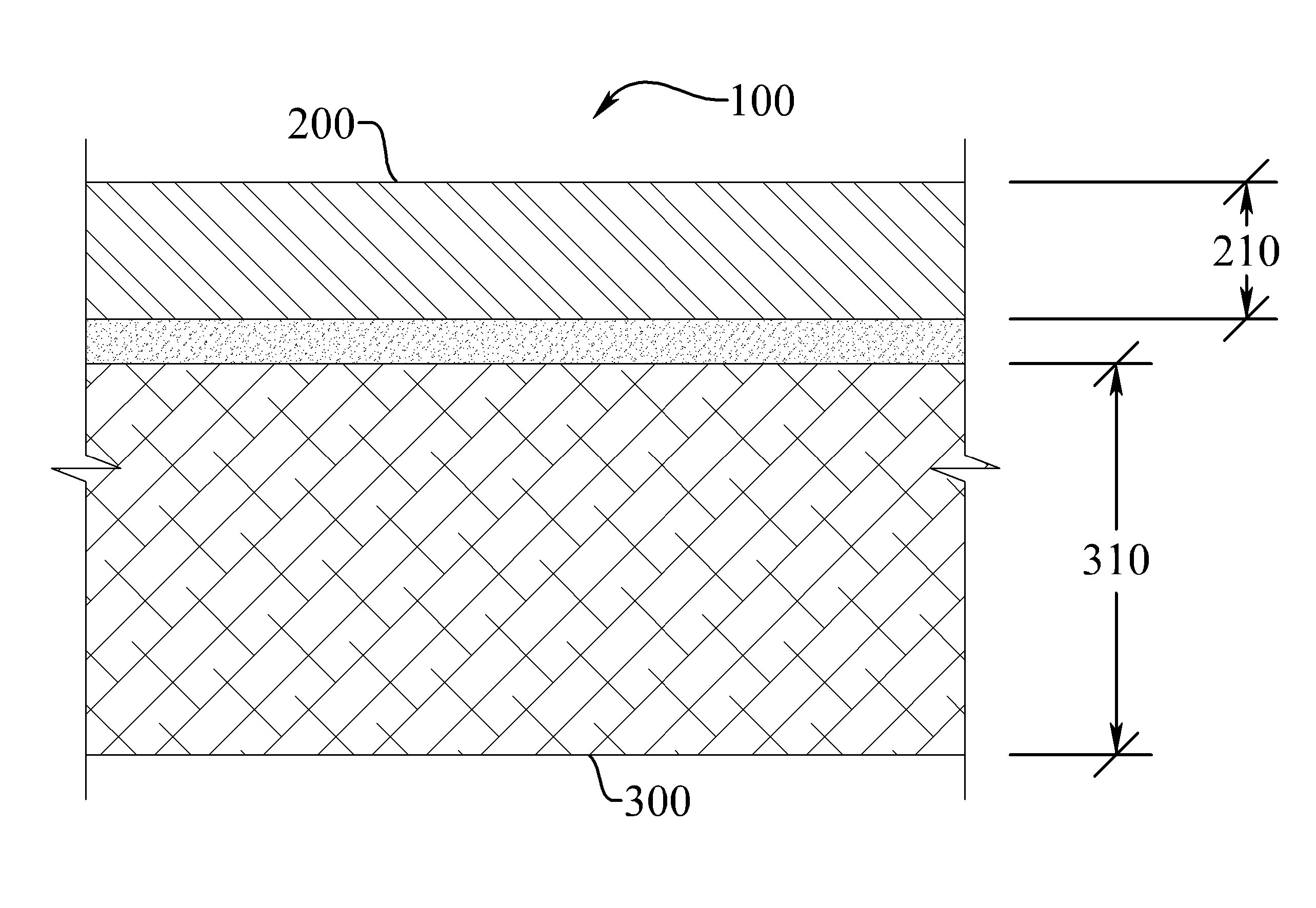
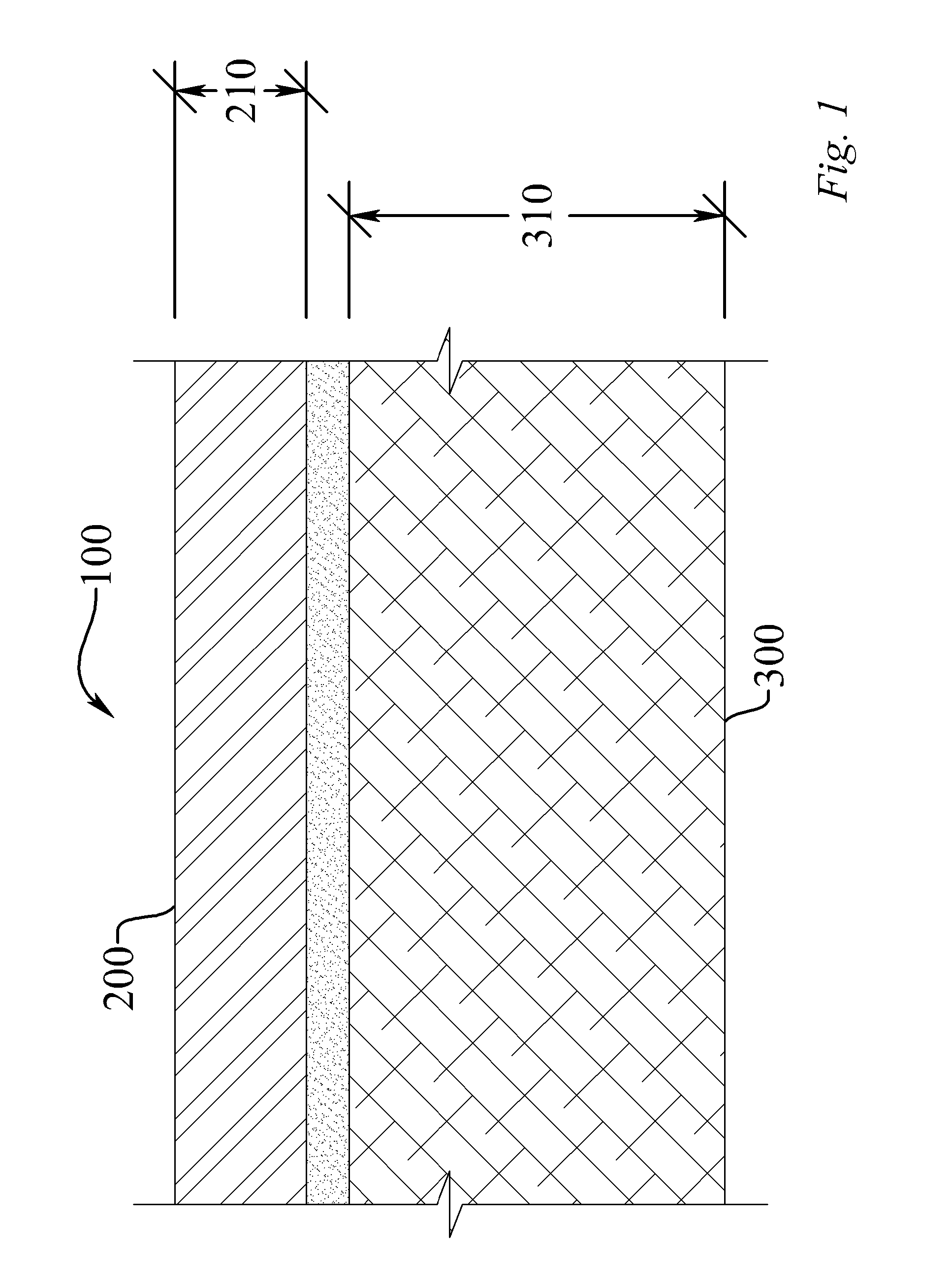
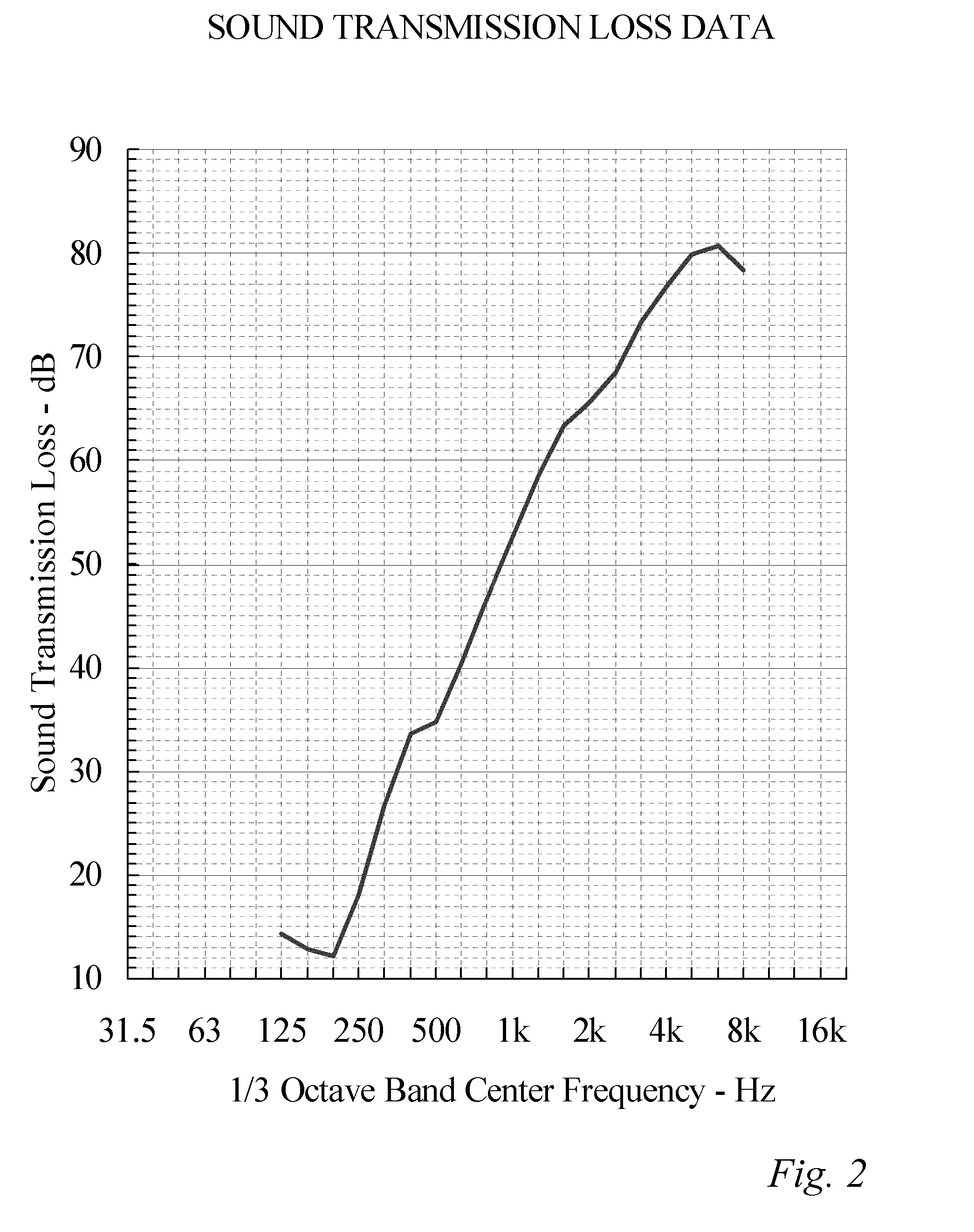
[0019]The present invention includes a thermally and acoustically insulative vehicle flooring system (100). The invention enables a significant advance in the state of the art. The preferred embodiments of the apparatus accomplish this by new and novel methods that are configured in unique and novel ways and which demonstrate previously unavailable but preferred and desirable capabilities. The description set forth below in connection with the drawings is intended merely as a description of the presently preferred embodiments of the invention, and is not intended to represent the only form in which the present invention may be constructed or utilized. The description sets forth the designs, functions, means, and methods of implementing the invention in connection with the illustrated embodiments. It is to be understood, however, that the same or equivalent functions and features may be accomplished by different embodiments that are also intended to be encompassed within the spirit a...


PUM

PropertyMeasurementUnit
densityaaaaaaaaaa
densityaaaaaaaaaa
densityaaaaaaaaaa

Abstract

A vehicle flooring system with improved thermal and acoustic properties is provided that does not unreasonably increase the thickness and weight of the flooring system and does not break down due to repeated exposure to high temperatures and wide ranging temperature fluctuations. Various materials and construction methods are combined to provide a system with optimized thermal conductivity, having varied density ratios of materials to meet particular sound transmission loss profiles. These materials include a wide range of foam and other materials.

Description

CROSS-REFERENCE TO RELATED APPLICATIONS[0001]This application claims the benefit of U.S. Provisional Patent Application Ser. No. 61 / 177,941; filed May 13, 2009, all of which is incorporated by reference as if completely written herein.STATEMENT REGARDING FEDERALLY SPONSORED RESEARCH OR DEVELOPMENT[0002]This invention was not made as part of a federally sponsored research or development project.TECHNICAL FIELD[0003]The present invention relates generally to the field of acoustical and thermal insulation and, more particularly, to a vehicle flooring system.BACKGROUND OF THE INVENTION[0004]Acoustical and thermal insulators and liners for application to vehicles are well known in the art. These insulators typically rely upon both sound absorption, i.e. the ability to absorb incident sound waves and transmission loss, and the ability to reflect incident sound waves, in order to provide sound attenuation. They also rely upon thermal shielding properties to prevent or reduce the transmissi...

Claims


Application Information

Patent Timeline
Patent Type & Authority Patents(United States)
IPC IPC(8): E04B1/82
CPCB32B25/00B60R13/083B32B5/18B32B9/02B32B9/043B32B9/045B32B25/045B32B25/047B32B25/14B32B27/065B32B27/14B32B27/304B32B27/32B32B27/34B32B2260/025B32B2260/04B32B2264/0292B32B2266/0207B32B2266/0235B32B2266/025B32B2266/0278B32B2266/06B32B2266/08B32B2307/102B32B2307/304B32B2307/306B32B2307/546B32B2307/718B32B2307/72B32B2605/00
Inventor MAY, PHILIP G.FISHEL, DONALD L.
Owner CVG MANAGEMENT
Learn More