
Wiring substrate with lead pin and lead pin

a technology of lead pins and wiring substrates, which is applied in the direction of conductors, sustainable manufacturing/processing, and final product manufacturing, etc., can solve the problems of heat resistance of the bonding part between the lead pin and the electrode pad, and the action of suppressing the void is not necessarily sufficient, so as to reduce the heat resistance and improve the reliability

Active Publication Date: 2012-04-10
SHINKO ELECTRIC IND CO LTD
View PDF13 Cites 10 Cited by
  • Summary
  • Abstract
  • Description
  • Claims
  • Application Information

AI Technical Summary

Benefits of technology

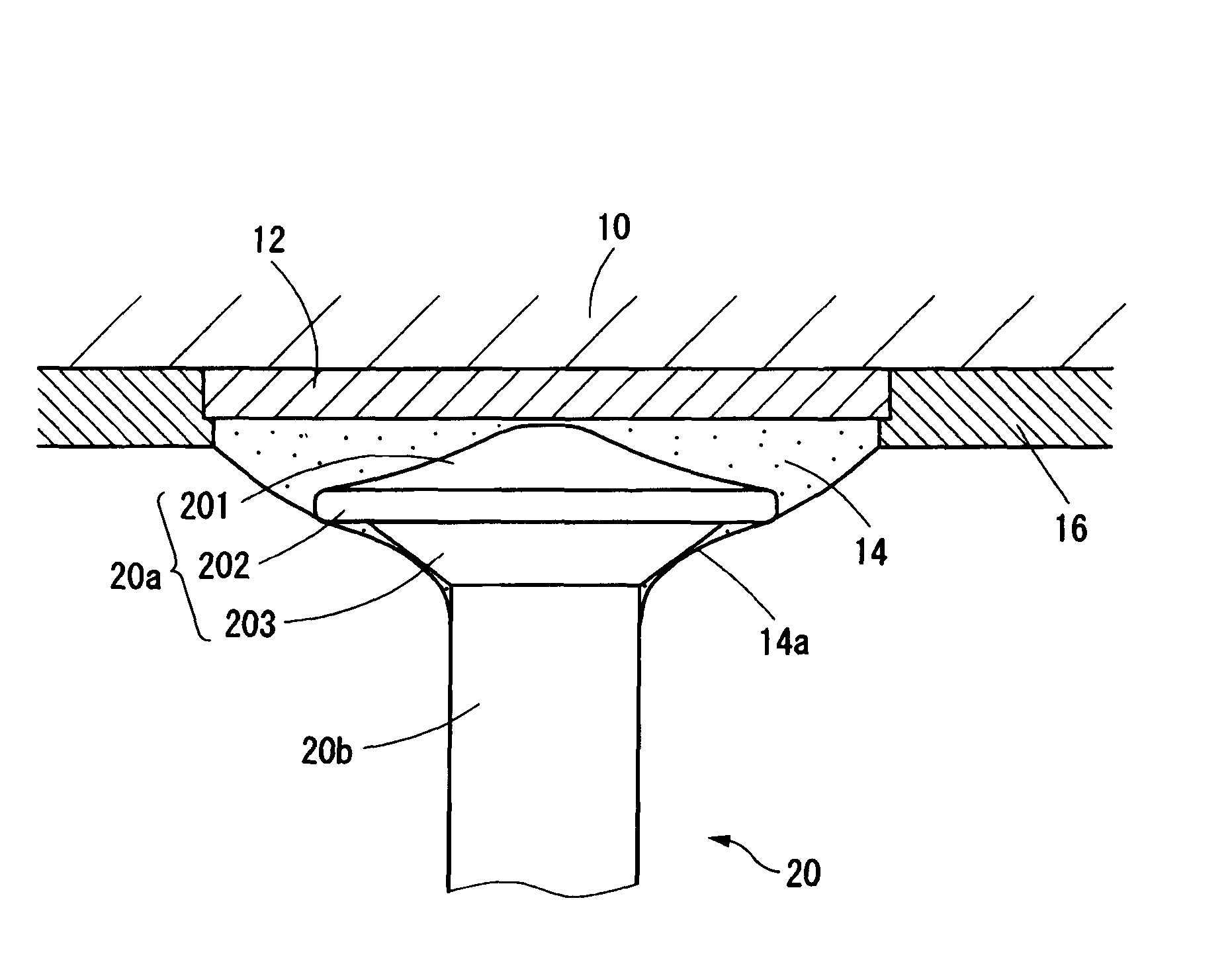
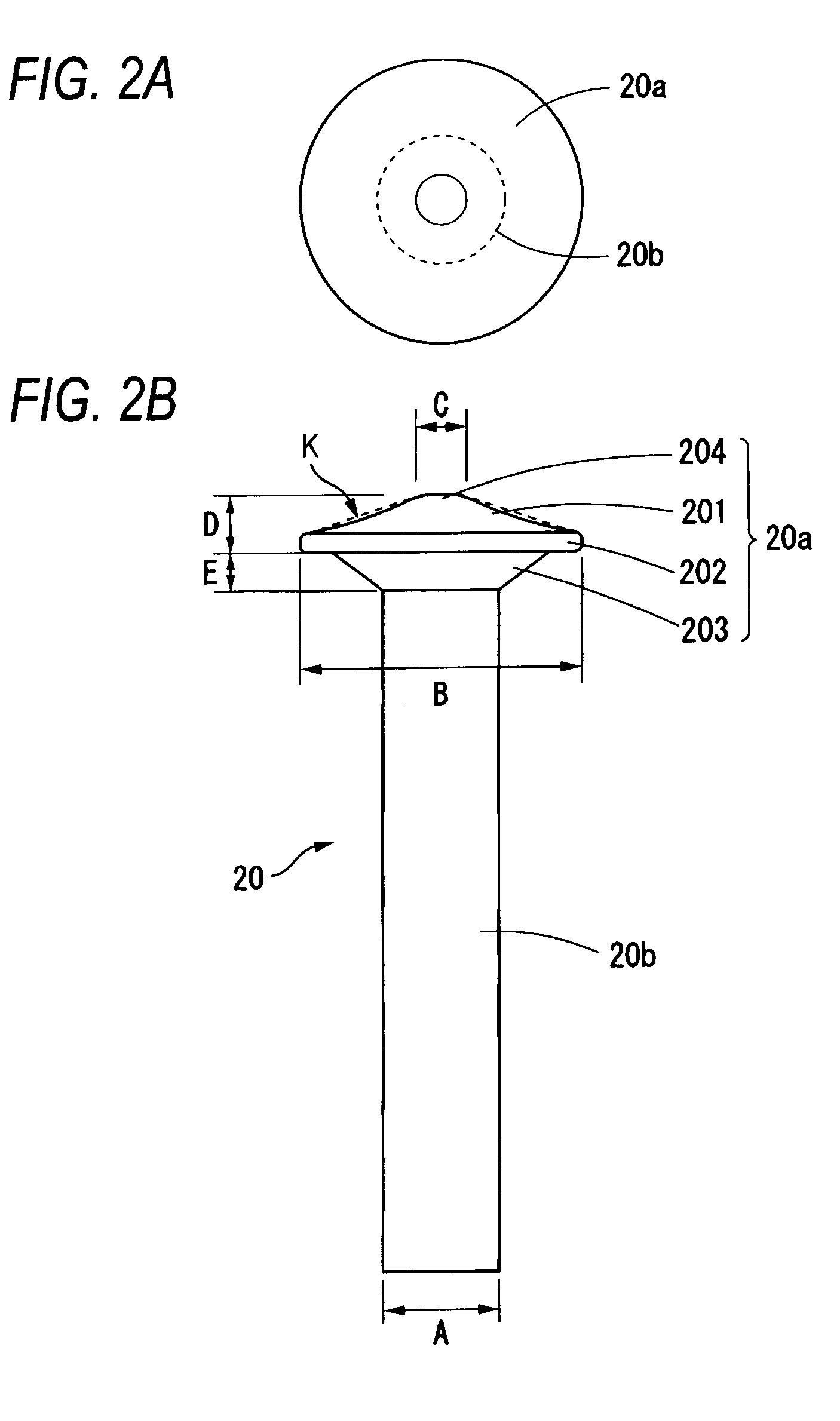
The present invention provides a wiring substrate with a lead pin that has improved reliability and reduced heat resistance. This is achieved by suppressing the occurrence of voids in the bonding part between the lead pin and electrode pad and reducing the amount of gold diffusing into the conductive material. The lead pin has a conic protrusion part with a concave surface in the end face side opposed to the electrode pad, and the conductive material extends beyond the flange part of the head part and reaches the shaft part of the lead pin, ensuring sure bonding. The lead pin can also have a flat or rounded top part. The use of a conic protrusion part with a concave surface in the head part of the lead pin and a flat or rounded top part improves reliability and reduces the risk of voids in the bonding part.

Problems solved by technology

However, in the lead pin comprising the related-art head part, action of suppressing occurrence of the void is not necessarily sufficient.
Also, the wiring substrate with lead pins is inserted into and withdrawn from a socket, so that a strength of bonding between the lead pin and the electrode pad becomes a problem.
However, in order to arrange the lead pins at a high density, a dimension of the head part is restricted, so that a lead pin capable of obtaining a necessary bonding strength without increasing a diameter of the head part is desired.
In addition, in the wiring substrate with lead pins, a step (die attachment step) of installing a semiconductor element is undergone after the lead pins are bonded to the wiring substrate, so that heat resistance of a bonding part between the lead pin and the electrode pad becomes a problem.
A conductive material having necessary heat resistance assuming the die attachment step is used in the conductive material for bonding the lead pin to the electrode pad, and gold plating is given to an outer surface of the lead pin as protective plating, so that there is a problem that in a step of bonding the lead pin, gold (Au) diffuses into the conductive material 14 and thereby heat resistance of the bonding part reduces.
When heat resistance of the bonding part between the lead pin and the electrode pad reduces, an obstacle may occur in a post-step of bonding a semiconductor element.

Method used


Image

  • Wiring substrate with lead pin and lead pin
  • Wiring substrate with lead pin and lead pin
  • Wiring substrate with lead pin and lead pin

Examples


Embodiment Construction

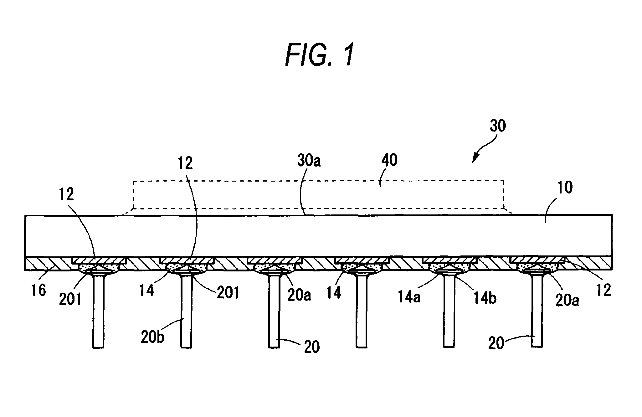
[0035]FIG. 1 is a sectional view showing a configuration of one embodiment of a wiring substrate with lead pins according to the invention. A wiring substrate 30 with lead pins of the present embodiment is formed by disposing an installation part 30a for installing a semiconductor element 40 on one surface of a wiring substrate 10 and forming electrode pads 12 on the other surface of the wiring substrate 10 and bonding lead pins 20 to the electrode pads 12 by conductive materials 14 made of tin-antimony alloys.

[0036]A necessary wiring pattern and a pad for connection electrically connected to the semiconductor element 40 are formed in the installation part 30a. The other surface of the wiring substrate 10 is covered with a protective film 16 such as a solder resist, and the electrode pad 12 to which the lead pin 20 is bonded is exposed in a circular plane shape. The electrode pad 12 is formed by a copper layer, and nickel plating and gold plating are given to a surface of the copper...


PUM

PropertyMeasurementUnit
diameteraaaaaaaaaa
diameteraaaaaaaaaa
melting temperatureaaaaaaaaaa

Abstract

A wiring substrate with a lead pin is formed by bonding lead pins to electrode pads formed on a wiring substrate through conductive materials. In the lead pin, a conic protrusion part whose side surface is formed in a concave surface is formed in the end face side opposed to the electrode pad of a head part formed in one end of a shaft part. The lead pin is bonded to the electrode pad in a state in which the conductive material extends to the back surface side of a head part beyond a flange part of the head part and reaches the shaft part of the lead pin.

Description

TECHNICAL FIELD[0001]The present disclosure relates to a wiring substrate with a lead pin and a lead pin, and more particularly to a pin grid array (PGA) type wiring substrate with lead pins formed by bonding lead pins to electrode pads, and lead pins used in this wiring substrate.RELATED ART[0002]A pin grid array type wiring substrate with lead pins includes a product provided by bonding lead pins 5, 6 to electrode pads 12 disposed in a wiring substrate 10 through conductive materials 14 such as solder as shown in FIGS. 9A and 9B. FIG. 9A is an example in which the lead pin 5 of the so-called flat pin type whose head part 5a is formed in a flat disk shape is bonded to the electrode pad 12 with the head part 5a abutted on the electrode pad 12. FIG. 9B is an example formed by bonding the lead pin 6 comprising a head part 6a in which the surface side of bonding to the electrode pad 12 is formed in a spherical surface to the electrode pad 12.[0003]In the case of bonding the lead pins 5...

Claims


Application Information

Patent Timeline
Patent Type & Authority Patents(United States)
IPC IPC(8): H01B5/00
CPCH01L23/49811H05K3/3426H01L2924/15312H01L2224/32225H05K2201/10318Y02P70/50
Inventor TAKEUCHI, HIROKAZUSHIMADA, KIYOTAKAEBE, MASAYOSHIFURIHATA, YOSHINORI
Owner SHINKO ELECTRIC IND CO LTD
Learn More