
Detection of defective pixels in an image sensor

a technology of image sensor and defective pixels, applied in the field of image sensors, can solve the problems of inability to account for the variations of pixel defects under different conditions, the initial calibration technique does not account for pixels that, while initially functional, later become defective, etc., and achieves low false alarm rate, high detection rate, and effective detection of clusters of defective pixels.

Active Publication Date: 2012-04-10
LIFESIZE INC
View PDF11 Cites 4 Cited by
  • Summary
  • Abstract
  • Description
  • Claims
  • Application Information

AI Technical Summary

Benefits of technology

This approach effectively detects defective pixels with a low false positive rate, distinguishing between pixel defects and local texture variations, and can be adapted for both hot and cold pixel detection in image sensors, improving the quality of images produced.

Problems solved by technology

However, given that every defective pixel may negatively affect every image produced using the image sensor, it is still desirable to minimize the effects of such defective pixels.
However, the initial calibration is time consuming, and permanently storing the locations of all the defective pixels in the sensor requires dedicating a certain amount of hardware to the problem.
In addition, calibration based techniques do not account for variations in pixel defects under different conditions, such as overall sensor gain and temperature.
Finally, initial calibration techniques do not account for pixels that, while initially functional, later become defective due to aging.
However, the existing methods in this area are simplistic and typically either have difficulty detecting clusters of defective pixels (i.e., adjacent defective pixels), or have difficulty distinguishing between local texture in an image and clusters of defective pixels, and in some cases have a high rate of false positives.

Method used


Image

  • Detection of defective pixels in an image sensor
  • Detection of defective pixels in an image sensor
  • Detection of defective pixels in an image sensor

Examples


Embodiment Construction

Terms

[0021]The following is a glossary of terms used in the present application:

[0022]Memory Medium—Any of various types of memory devices or storage devices. The term “memory medium” is intended to include an installation medium, e.g., a CD-ROM, floppy disks, or tape device; a computer system memory or random access memory such as DRAM, DDR RAM, SRAM, EDO RAM, Rambus RAM, etc.; or a non-volatile memory such as a PROM, EPROM, EEPROM, flash memory, or magnetic media, e.g., a hard drive, or optical storage. The memory medium may comprise other types of memory as well, or combinations thereof. In addition, the memory medium may be located in a first computer in which the programs are executed, and / or may be located in a second different computer which connects to the first computer over a network, such as the Internet. In the latter instance, the second computer may provide program instructions to the first computer for execution. The term “memory medium” may include two or more memory...


PUM


Abstract

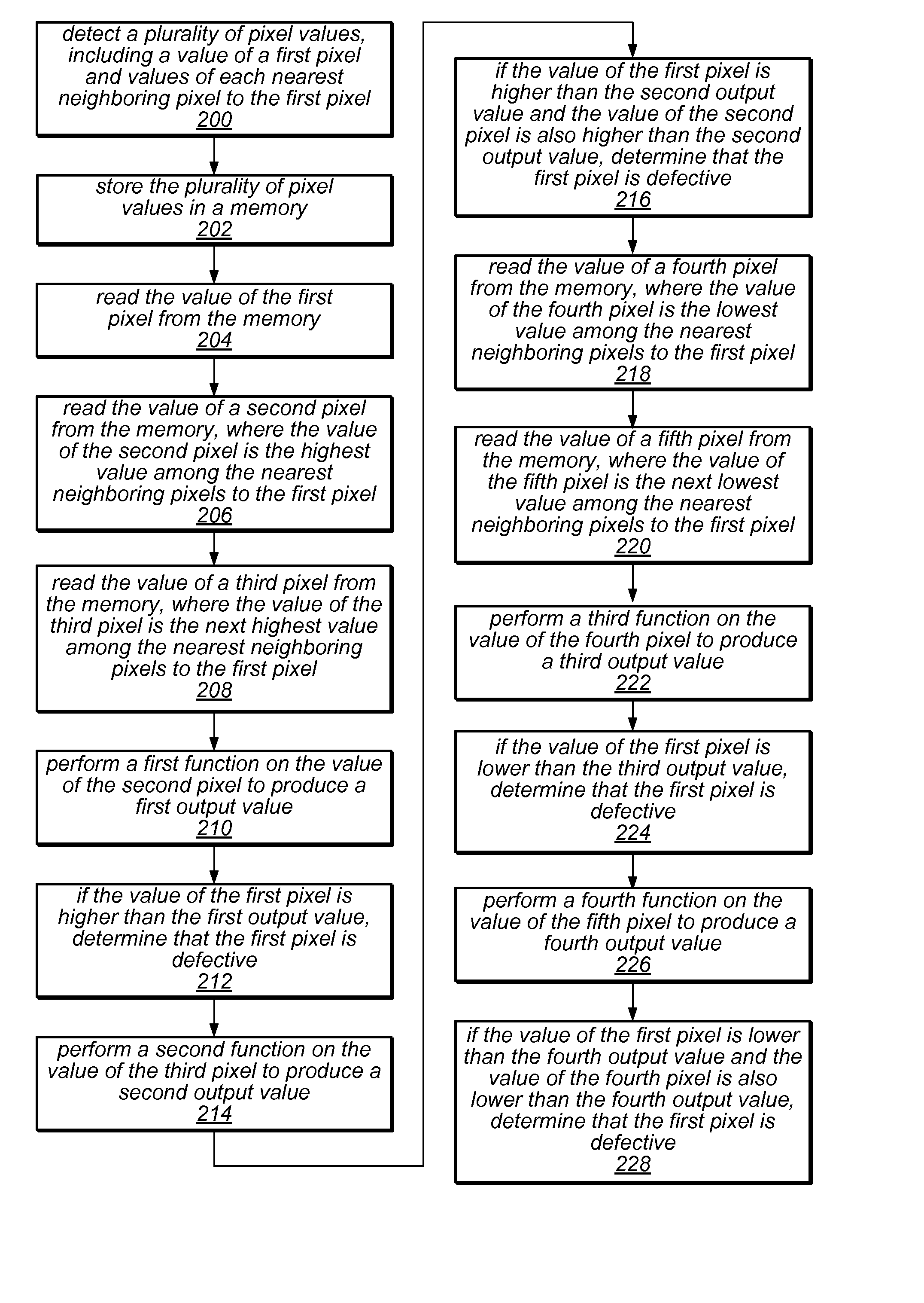
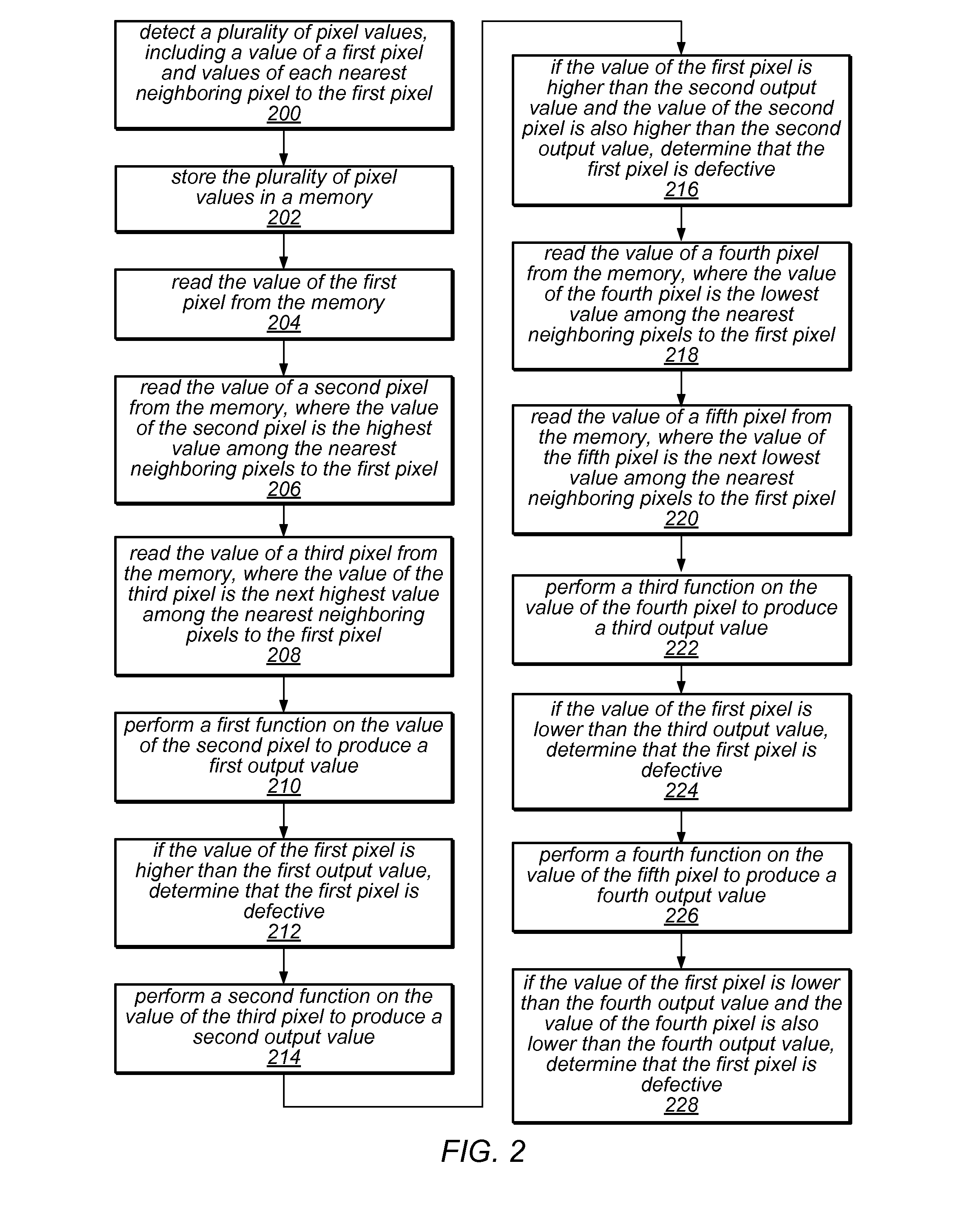
A system and method for detecting defective pixels in a sensor. A plurality of pixel values of the sensor may be detected. The values may include those of a first pixel and each nearest neighboring pixel to the first pixel. A second pixel may have the highest value of the neighboring pixels. A third pixel may have the next highest value of the neighboring pixels. A first function may be performed on the second pixel value, producing a first output value. A second function may be performed on the third pixel value, producing a second output value. If the first pixel value is higher than the first output value, or, if the first pixel value is higher than the second output value and the second pixel value is higher than the second output value, it may be determined that the first pixel is defective.

Description

FIELD OF THE INVENTION[0001]The present invention relates to image sensors, and in particular to detection of defective pixels in an image sensor.DESCRIPTION OF THE RELATED ART[0002]The growing fields of digital photography and digital videography typically rely on the use of digital image sensors to detect an image. A digital image sensor typically includes of a field of light sensitive pixels. As it is very difficult to manufacture image sensors that are entirely free from defects, a certain number of defective pixels is generally considered acceptable in the manufacture of digital image sensors as a trade off in exchange for reducing the cost of manufacturing. However, given that every defective pixel may negatively affect every image produced using the image sensor, it is still desirable to minimize the effects of such defective pixels.[0003]One way to account for defective pixels is to calibrate a sensor, initially detecting and subsequently remembering the locations of any def...

Claims


Application Information

Patent Timeline
Patent Type & Authority Patents(United States)
IPC IPC(8): H04N9/64
CPCH04N5/3675H04N25/683
Inventor MCKINNON, PATRICK R.FLOSDORF, STEPHEN P.LI, JINGQIANG
Owner LIFESIZE INC
Learn More