
Delivery of therapeutic and marking substance through intra lumen expansion of a delivery device

a delivery device and intra-luminescent expansion technology, applied in the field of balloon catheters, can solve the problems of only delivering a therapeutic substance, thomas does not disclose the advantages, and the treatment period is therefore necessarily short, so as to promote a uniform contact pressure

Active Publication Date: 2012-04-24
JAYARAMAN SWAMINATHAN
View PDF26 Cites 16 Cited by
  • Summary
  • Abstract
  • Description
  • Claims
  • Application Information

AI Technical Summary

Benefits of technology

"The invention is a balloon catheter that can deliver a therapeutic substance to a body lumen. The balloon has depressions or reservoirs where the substance can be placed, and the substance can be transferred to the lumen wall when the balloon is inflated. The balloon can also have a rough surface to create reservoirs for the substance. The catheter can be guided by a guide wire and can maintain blood flow while inflated. The coating on the balloon can be micropipeted or transferred to the lumen wall. The balloon catheter can be used to deliver a therapeutic substance without leaving an implant or device in the body. The invention also includes a wire frame that helps ensure uniform contact pressure with the lumen wall. The wire frame can be removed with the balloon at the end of the procedure."

Problems solved by technology

In Klein, however, the application of a therapeutic substance only takes place while the balloon is inflated.
Thus, the period of treatment is thus necessarily short, and terminates once the surgical procedure is over, and the catheter is removed.
Thomas does not disclose the advantages of delivering a substance using a balloon catheter itself as the delivery device.
Where it is not necessary to leave an implant in the body, however, Thomas fails to provide a solution.
Again, however, delivery is effectively halted when the balloon is removed.

Method used


Image

  • Delivery of therapeutic and marking substance through intra lumen expansion of a delivery device
  • Delivery of therapeutic and marking substance through intra lumen expansion of a delivery device
  • Delivery of therapeutic and marking substance through intra lumen expansion of a delivery device

Examples


Embodiment Construction

[0045]In the description which follows, any reference to direction or orientation is intended primarily and solely for purposes of illustration and is not intended in any way as a limitation to the scope of the present invention. Also, the particular embodiments described herein, although being preferred, are not to be considered as limiting of the present invention.

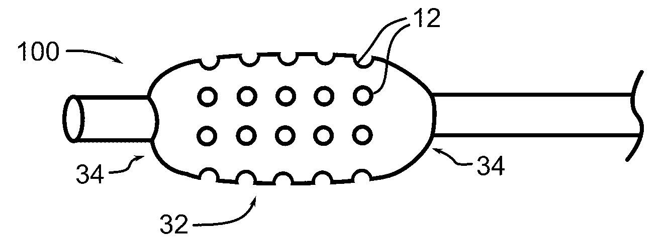
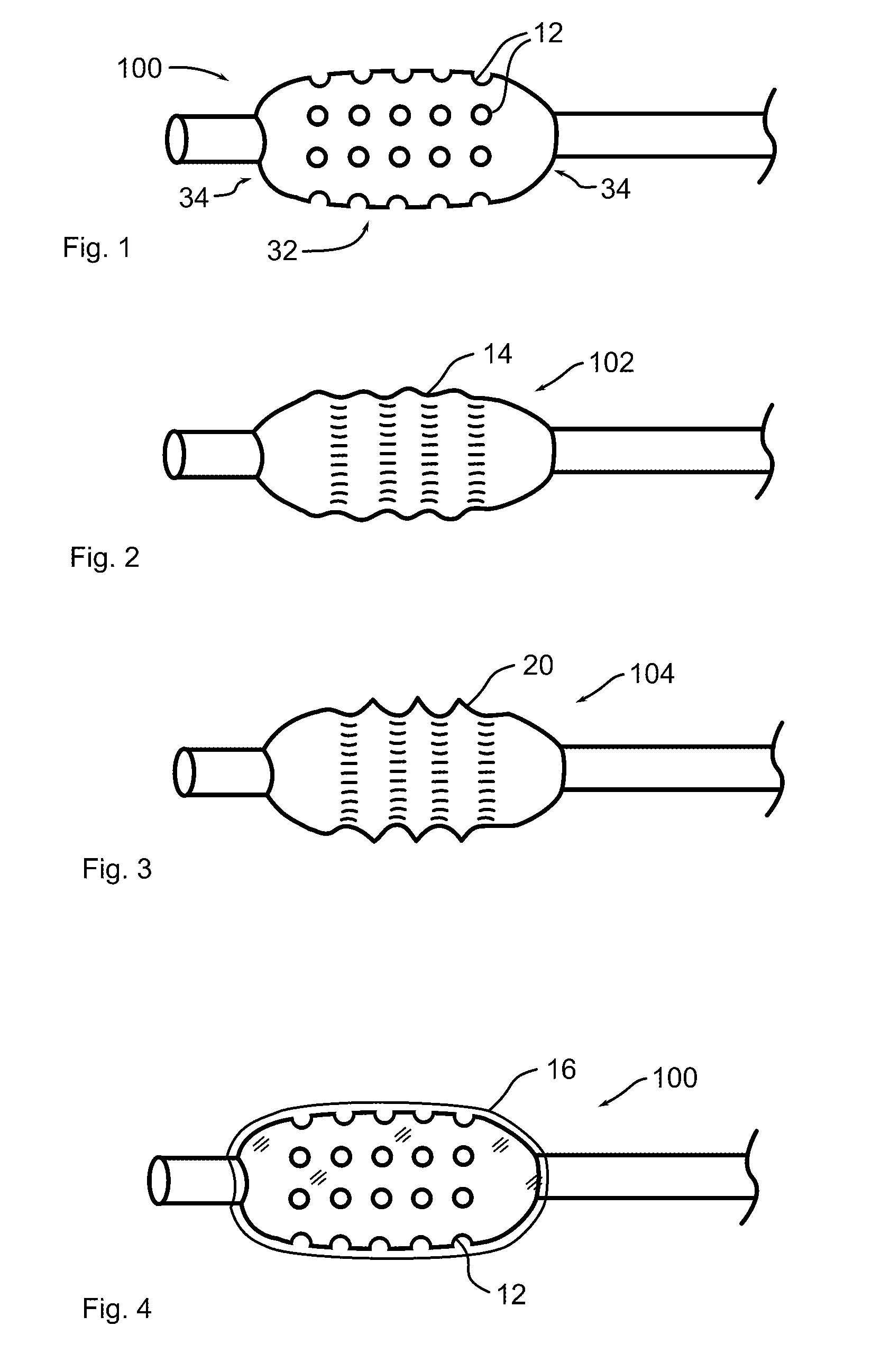
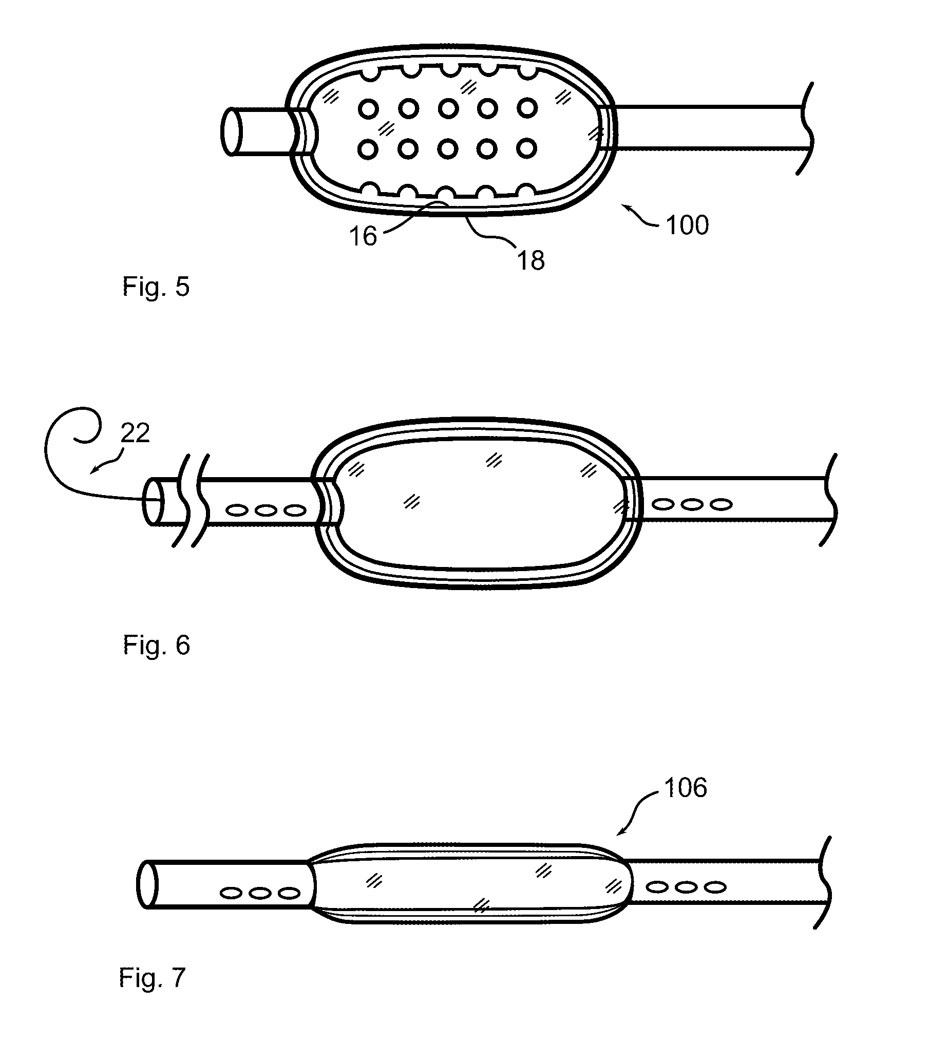
[0046]Referring now to the figures in which like reference numerals refer to like elements, an exemplary balloon catheter 100 in accordance with the invention is illustrated in FIG. 1. Balloon 100 is formed with a plurality of depressions, wells or reservoirs 12, into which a therapeutic substance is placed. When the balloon is expanded within a body lumen 200, the therapeutic substance may infuse, diffuse, elute, or physically transfer to the lumen wall. In the illustration, large reservoirs 12 are shown for clarity. In practice, reservoirs 12 may be significantly smaller and more numerous.

[0047]Balloons are typically m...


PUM


Abstract

A balloon catheter is formed with a plurality of depressions. The balloon is coated with a matrix incorporating a therapeutic substance, which additionally fills the depressions. When the balloon is expanded within a body lumen, the therapeutic substance may diffuse into the lumen wall, or all or a portion of the coating transfers to the lumen wall. A lattice frame may surround the balloon, applied prior to coating if the coating is to transfer, operative to maintain a more linear balloon profile during inflation, promoting more even transfer pressure. A contrast dye is incorporated into the transferred coating, enabling ready location and inspection of the treated lumen area. Projections may alternately be formed in the balloon surface, operative to urge the coating and therapeutic substance between cells, or past cell layers of the lumen, to the interior of the lumen wall. Prior to transfer, an extended inflation period, possibly including the use of perfusion ports to maintain blood supply, enables a larger initial quantity of therapeutic substance to diffuse into the body lumen, prior to transfer of the coating and withdrawal of the catheter, balloon, and frame.

Description

FIELD OF THE INVENTION[0001]The present invention relates to balloon catheters for distal drug delivery within the body, wherein the balloon catheter applies a therapeutic substance to the interior surface of a body lumen upon inflation therein.BACKGROUND OF THE INVENTION[0002]The human body includes arterial and venous conduits which run throughout various sections of the human body. These conduits conduct blood into and from the heart which maintain the circulation that helps to sustain the metabolic events in the body. The vessels undergo biological, physiological, and mechanical changes depending on the body metabolism which determine the functionality of the wall of the artery.[0003]Sometimes the wall of an artery becomes occluded due to deposits of fatty tissues which in turn form plaque on the walls of the artery. These plaques then have to be removed to restore the normal function of the artery. One known mechanism of removing the plaque is to compress the plaque against the...

Claims


Application Information

Patent Timeline
Patent Type & Authority Patents(United States)
IPC IPC(8): A61M31/00A61M37/00A61F2/958
CPCA61M25/1002A61M25/1027A61F2/958A61F2250/0067A61M2025/105A61M2025/1088A61M2025/1095
Inventor JAYARAMAN, SWAMINATHAN
Owner JAYARAMAN SWAMINATHAN
Learn More