Vascular filter

a filter and vascular technology, applied in the field of vascular filters, can solve the problems of pulmonary embolism (pe), not all surgical patients receive appropriate protection, and the diagnosis of pe is missed in approximately 70% of those patients, so as to facilitate the collapse of the support member

Active Publication Date: 2012-04-24
BOSTON SCI MEDICAL DEVICE LTD +1
View PDF77 Cites 42 Cited by
  • Summary
  • Abstract
  • Description
  • Claims
  • Application Information

AI Technical Summary

Benefits of technology

[0023]By capturing the thrombus, the filter prevents the thrombus from passing to the heart or lungs, which may cause pulmonaryembolism.
[0025]In one embodiment of the invention the support member is configured to extend circumferentially around a wall of a blood vessel. The support member may extend circumferentially in a wave pattern. The support member may extend circumferentially in a zigzag pattern. The support member may extend circumferentially in a crown pattern. The support member may extend circumferentially in a sinusoid pattern. The wave / sinusoid pattern of the support member facilitates collapse of the support member for ease of delivery and / or retrieval through the blood vessel. The support member may be configured to extend longitudinally along a wall of a blood vessel. A distal end of the support member may be located distally of a distal end of the capture member. A proximal end of the support member may be located proximally of a proximal end of the capture member. The filter may comprise a first support member configured to extend circumferentially around a wall of a blood vessel, a second support member configured to extend circumferentially around the wall of the blood vessel, and a third support member configured to extend longitudinally along the wall of the blood vessel. The third support member may connect the first support member to the second support member. The first support member, the second support member and the third support member may be formed integrally. The first support member may be provided at the proximal end of the filter. The second support member may be provided at the distal end of the filter.
[0035]In another embodiment the capture member extends towards an apex. In the capturing configuration, the capture member may extend towards the apex. The apex may be substantially in-line with a longitudinal axis extending through the centre of a blood vessel. The apex may be substantially offset from a longitudinal axis extending through the centre of a blood vessel. The offset apex may result in the captured thrombus being offset from the centre of the blood vessel. Thus blood flow through the blood vessel may be enhanced. Two or more of the capture members may engage one another at the apex. An end of a first capture member may be configured to nest with an end of a second capture member at the apex. The capture member may extend in the direction of blood flow through a blood vessel. The capture member may extend in a direction opposite to the direction of blood flow through a blood vessel. The capture member may extend in a spiral towards the apex. At least part of the capture member may extend in a curve. The convex portion of the curve may face radially outwardly. The concave portion of the curve may face radially outwardly.
[0056]IVC filter placement may be used as a prophylactic means for preventing PE in patients at high risk for thromboembolic events. The invention in suit greatly aids the use of filters during a period of high risk for thromboembolic events.

Problems solved by technology

When blood clots float from a large vein in the lower body through the vena cava to the heart and lungs they may cause pulmonary embolism (PE).
However, the diagnosis of PE is missed in approximately 70% of those patients.
In spite of the potentially disastrous outcomes, not all surgical patients receive appropriate protection.
This is in part due to the fact that current treatments are not ideal.
Retrievable filters can be notoriously difficult to remove and the additional intervention poses risks to patients.

Method used


Image

  • Vascular filter
  • Vascular filter
  • Vascular filter

Examples


Embodiment Construction

[0130]In this patent specification, the term “proximal” will be understood to mean the end closest to a user when carrying out a procedure accessed from a femoral vein, or the caudal end. Similarly the term “distal” will be understood to mean the end furthest from a user when carrying out a procedure accessed from a femoral vein, or the cranial end.

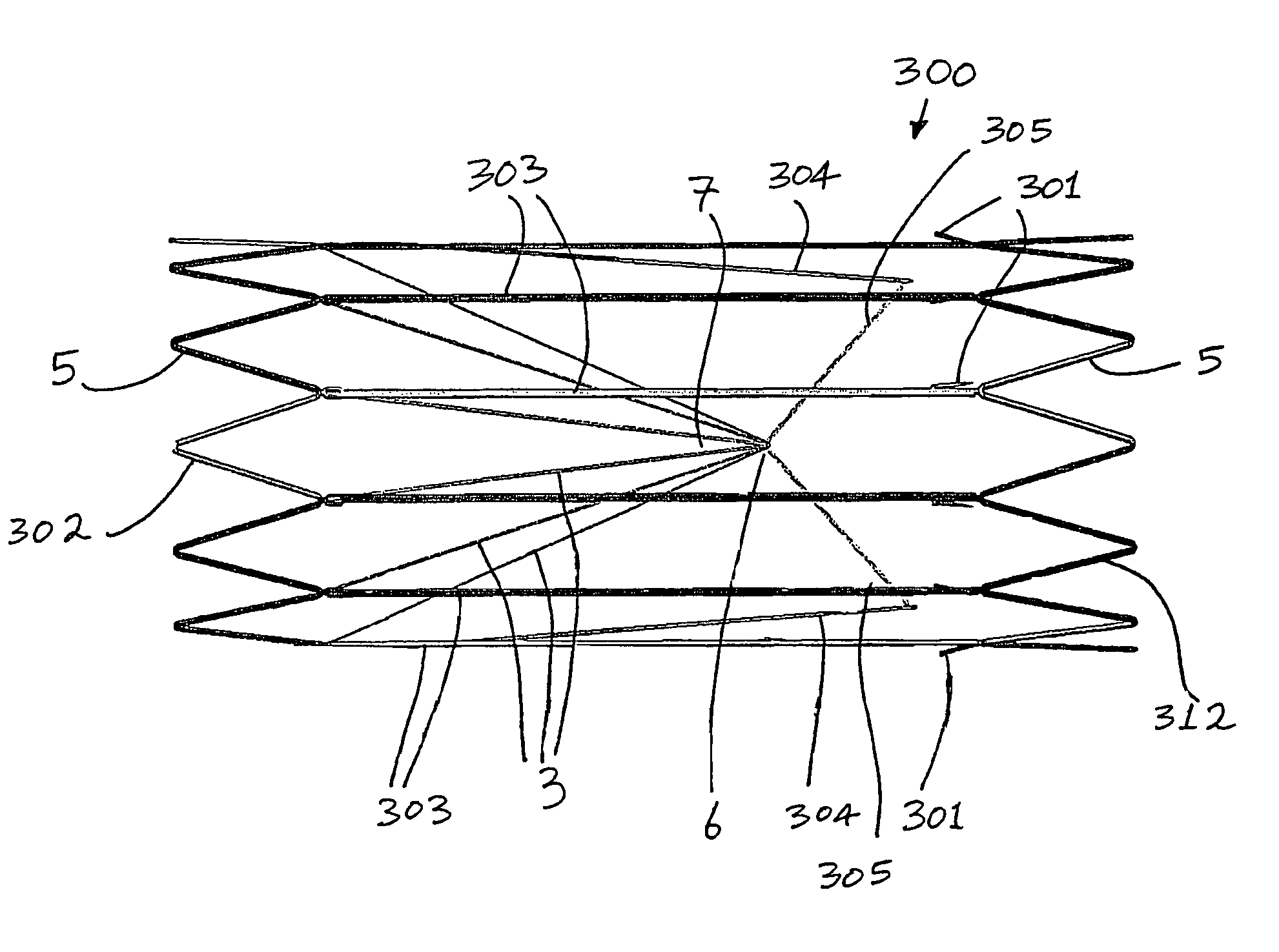
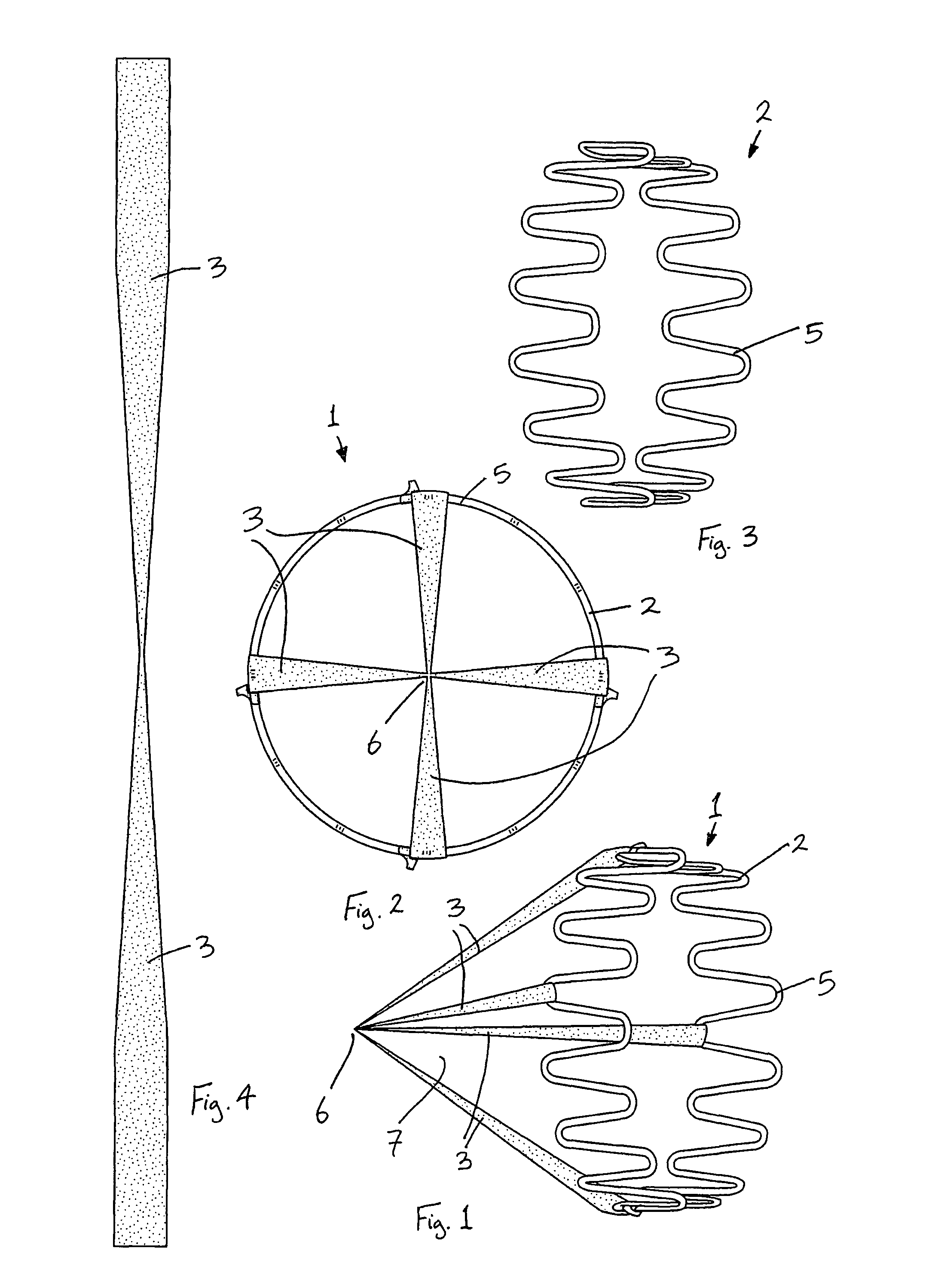
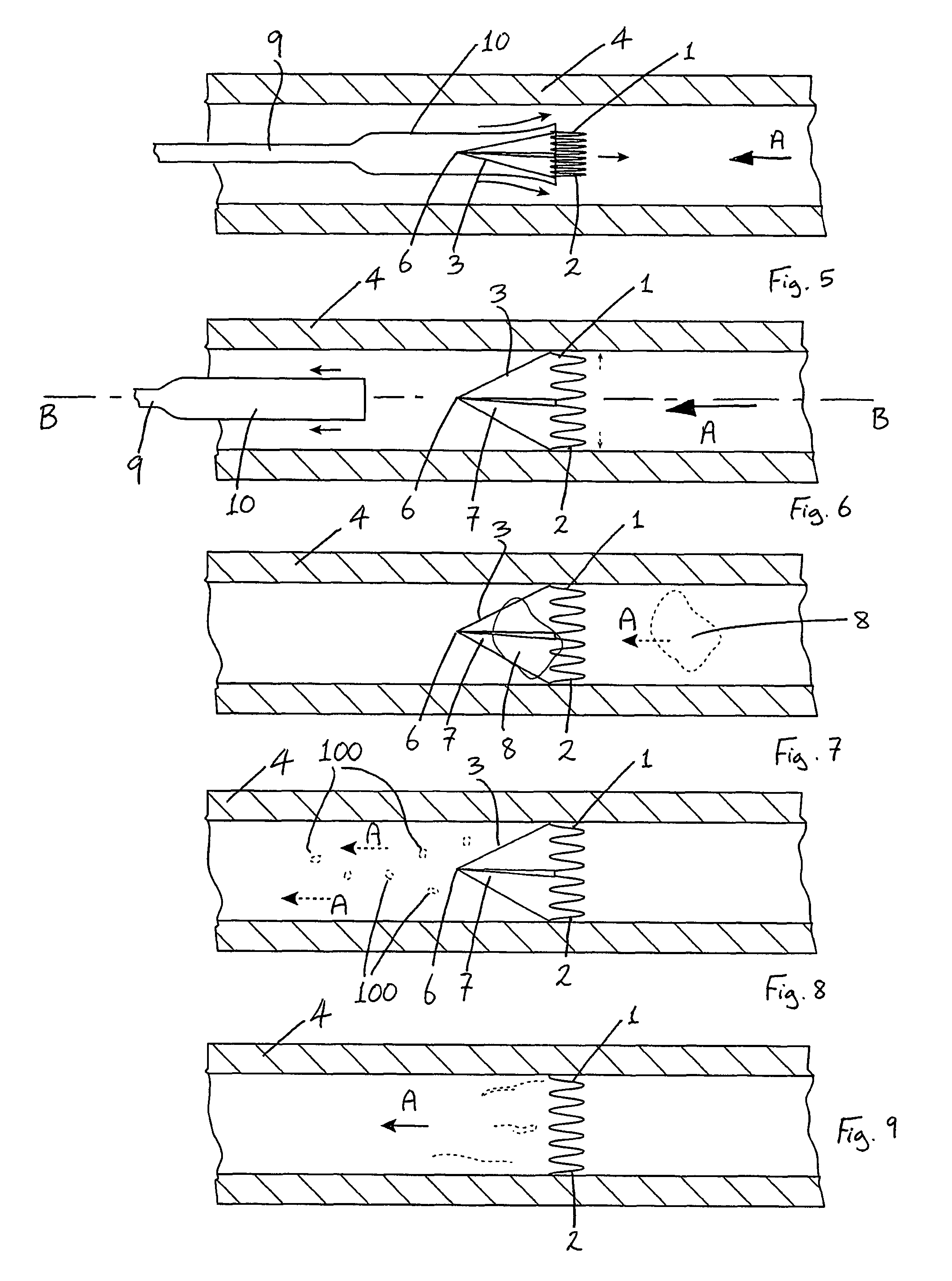
[0131]Referring to the drawings, and initially to FIGS. 1 to 9 thereof, there is illustrated a vascular filter assembly according to the invention. The vascular filter assembly comprises a vascular filter 1 according to the invention and a delivery catheter 9 for delivering the filter 1 to a desired location in a blood vessel, such as the inferior vena cava 4. The vascular filter 1 is suitable for use as an inferior vena cava filter in the inferior vena cava 4 to capture thrombus 8 passing through the inferior vena cava 4 towards the heart and the lungs. The vascular filter 1 may thus be used to prevent pulmonaryembolism.

[0132]The filter ...


PUM

PropertyMeasurementUnit
diameteraaaaaaaaaa
diameteraaaaaaaaaa
diameteraaaaaaaaaa

Abstract

An inferior vena cava filter (340) for use in the inferior vena cava (4) to capture thrombus (8) passing through the inferior vena cava (4) towards the heart and lungs to prevent pulmonary embolism comprises a proximal support hoop (302), a distal support hoop (312) and a plurality of support struts (303) extending between the proximal support hoop (302) and the distal support hoop (312). The filter (340) also comprises a plurality of capture arms (121) which are movable from a capturing configuration to an open configuration. The capture arms (121) are biased towards the open configuration. A biodegradable suture holds the capture arms (121) in the capturing configuration.

Description

CROSS REFERENCE TO RELATED APPLICATION[0001]This application claims the benefit of U.S. Provisional Application No. 60 / 831,674, filed on Jul. 19, 2006, the content of which is incorporated herein by reference.INTRODUCTION[0002]This invention relates to a vascular filter. In one particular embodiment this invention relates to an inferior vena cava filter.[0003]It is known to implant a vena cava filter in the vena cava to prevent thrombus entering the right atrium. They have been in use clinically for a number of years. The use of filters implanted in the inferior vena cava is for the prevention of pulmonary embolism in high-risk patients.[0004]Deep vein thrombosis (DVT) and pulmonary embolism (PE) are common medical conditions that contribute substantially to individual patient morbidity and mortality as well as global healthcare costs. DVT develops within the deep veins of the lower extremities but also can involve or arise solely from the veins of the pelvis or the upper extremitie...

Claims


Application Information

Patent Timeline
Patent Type & Authority Patents(United States)
IPC IPC(8): A61M29/00
CPCA61F2/01A61F2/86A61F2002/011A61F2210/0004A61F2002/016A61F2230/0006A61F2230/0021A61F2230/005A61F2230/0058A61F2230/0067A61F2230/0069A61F2230/008A61F2230/0091A61F2/011A61F2/0103A61F2/0105B01D61/00
Inventor GILSON, PAULTAYLOR, CHARLESHORAN, STEVENGILLESPIE, CIARA
Owner BOSTON SCI MEDICAL DEVICE LTD
Why Eureka
Try Eureka