
Motor drive control apparatus and method

a control apparatus and motor technology, applied in the direction of motor/generator/converter stopper, dynamo-electric gear control, dynamo-electric converter control, etc., can solve the problem that the feedback control for phase adjustment in the application of square wave control method may not ensure the output of maximum torqu

Active Publication Date: 2012-04-24
TOYOTA JIDOSHA KK +1
View PDF8 Cites 2 Cited by
  • Summary
  • Abstract
  • Description
  • Claims
  • Application Information

AI Technical Summary

Benefits of technology

[0014]a target voltage phase setting module configured to set a target voltage phase of the square wave voltage within a phase range defined by the limit phases set by the limit phase setting module, so as to reduce a torque difference between the target torque and the output torque of the AC motor; and
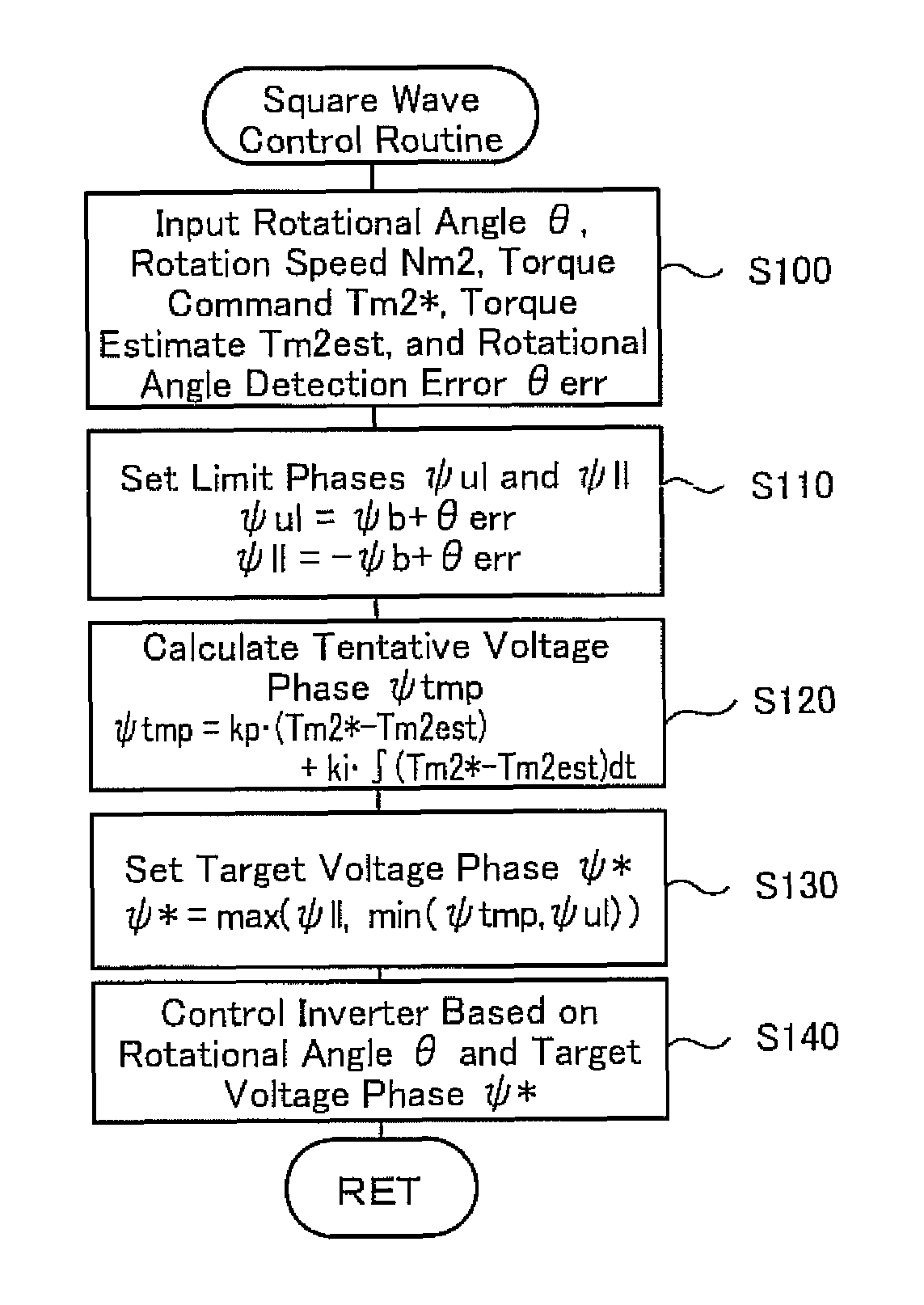
[0034]As described, the motor drive control apparatus of this aspect corrects the limit phases of the square wave voltage according to the relation of the torque actually output from the AC motor to the setting condition of the phase of the square wave voltage, and sets the target voltage phase of the square wave voltage within the phase range defined by the limit phases. This arrangement effectively prevents the actual phase of the square wave voltage from being out of the range defined by the phases for maximizing the absolute value of the output torque due to any of various causes. The arrangement of this aspect ensures output of a torque, which is expected to be output from the AC motor.

Problems solved by technology

The feedback control for phase adjustment in application of the square wave control method may, however, not ensure output of a maximum torque, which is expected to be output from the AC motor in a certain condition.

Method used


Image

  • Motor drive control apparatus and method
  • Motor drive control apparatus and method
  • Motor drive control apparatus and method

Examples


Embodiment Construction

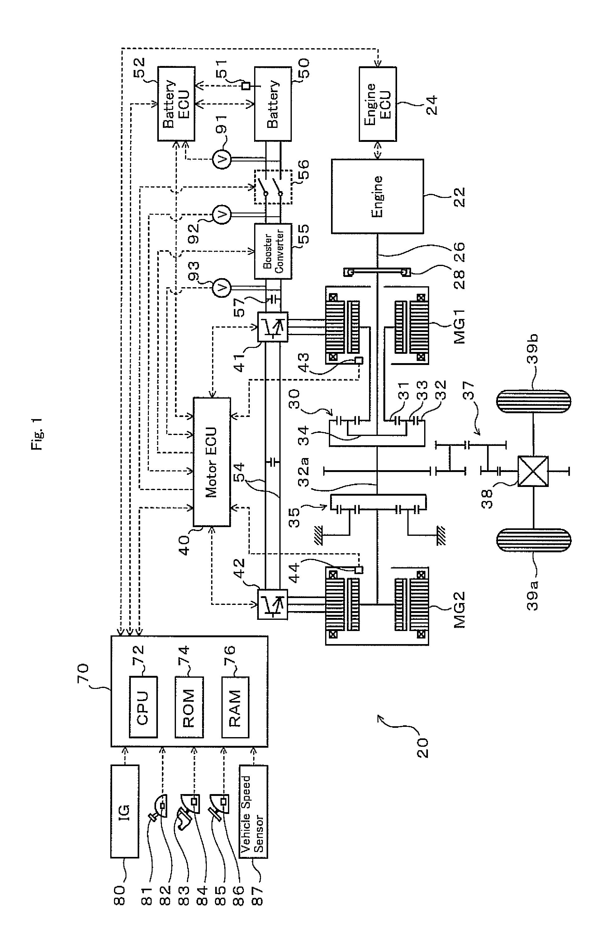
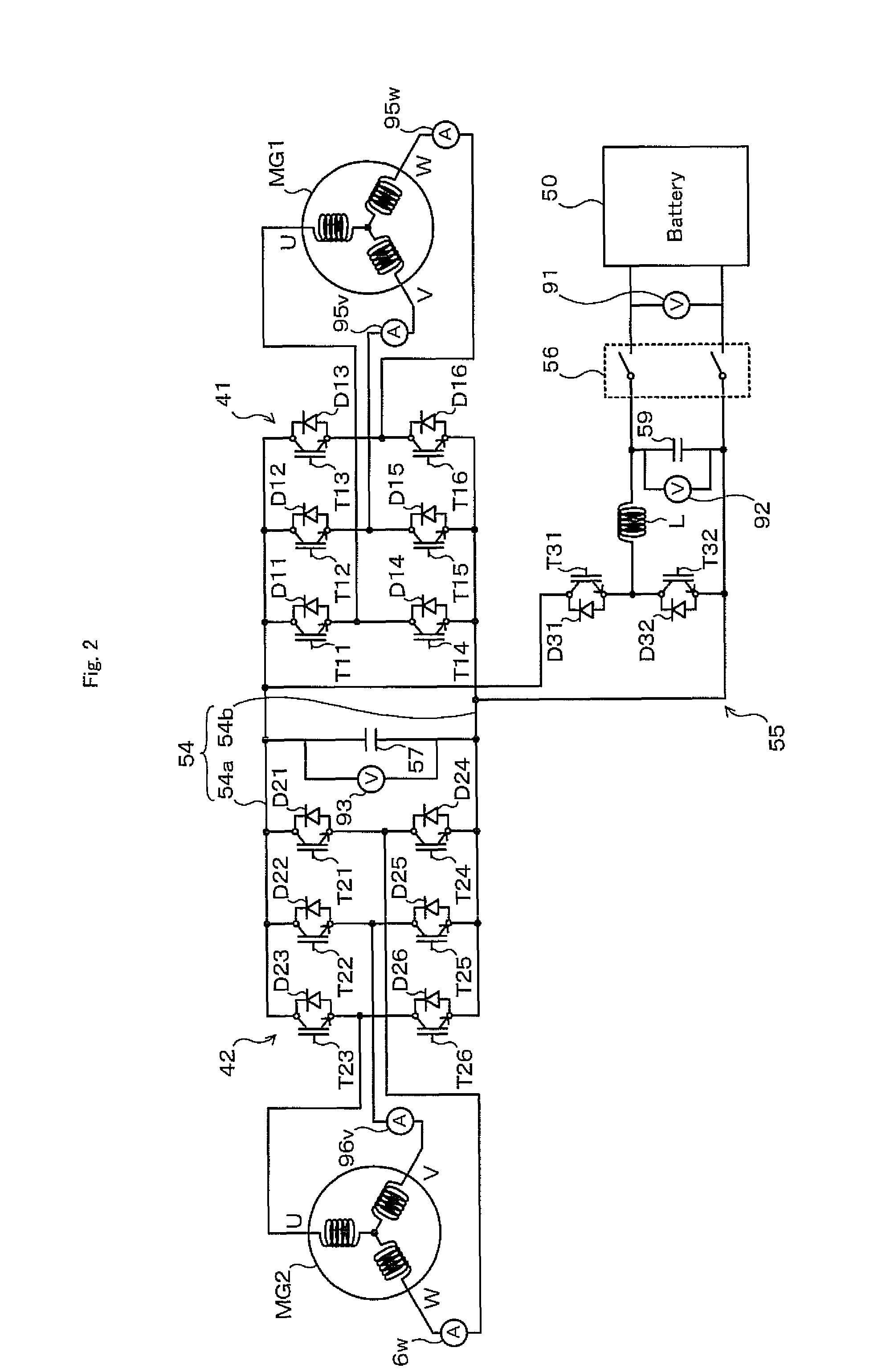
[0042]FIG. 1 schematically illustrates the configuration of a hybrid vehicle 20 equipped with a motor drive control apparatus in one embodiment of the invention. FIG. 2 shows the schematic structure of a motor drive control system included in the hybrid vehicle 20. As illustrated, the hybrid vehicle 20 of the embodiment includes an engine 22, a three shaft-type power distribution integration mechanism 30 connected via a damper 28 to a crankshaft 26 or an output shaft of the engine 22, a motor MG1 connected with the power distribution integration mechanism 30 and designed to have power generation capability, a reduction gear 35 attached to a ring gear shaft 32a as an axle linked with the power distribution integration mechanism 30, a motor MG2 connected to the ring gear shaft 32a via the reduction gear 35, inverters 41 and 42 arranged to convert direct-current power into alternating-current power and supply the alternating-current power to the motors MG1 and MG2, a booster converter ...


PUM


Abstract

In application of a square wave voltage to a motor MG2 to make the motor MG2 output a torque equivalent to a torque command Tm2*, the procedure of square wave control corrects reference phases ψb and −ψb as phases for maximizing an absolute value of the output torque of the motor MG2 with a rotational position detection error θerr and sets the results of the correction to an upper limit phase ψul and a lower limit phase ψll of the square wave voltage (step S110). A target voltage phase ψ* is set within a phase range defined by the upper limit phase ψul and the lower limit phase ψll, in order to reduce a torque difference between the torque command Tm2* and a torque estimate Tm2est (steps S120 and S130). An inverter 42 is controlled based on the target voltage phase ψ* and a rotational angle θ of the motor MG2.

Description

[0001]This Application claims priority of Japanese Patent Application No. 2008-176023 filed on Jul. 4, 2008, which is incorporated herein by reference.BACKGROUND OF THE INVENTION[0002]1. Field of the Invention[0003]The present invention relates to a motor drive control apparatus configured to control operations of an AC motor, as well as to a corresponding motor drive control method.[0004]2. Description of the Prior Art[0005]One proposed motor drive control apparatus disclosed in Japanese Patent Laid-Open No. 2007-159368 is equipped with an inverter for driving an AC motor and, in response to selection of a first control method of applying a square wave voltage to the AC motor, performs feedback control to adjusting the phase of the square wave voltage according to a torque difference relative to a torque command value. This prior art motor drive control apparatus estimates an output torque of the AC motor based on the motor electric current and the rotational position of a rotor in...

Claims


Application Information

Patent Timeline
Patent Type & Authority Patents(United States)
IPC IPC(8): H02P23/12H02P21/18H02P21/24H02P23/14H02P27/06
CPCH02P6/08H02P6/10
Inventor YAMADA, KENJIKAKO, HIROFUMIITOH, TAKESHI
Owner TOYOTA JIDOSHA KK
Learn More