Method and apparatus for steam generation

a technology of steam generation and steam boiler, applied in the direction of steam boiler components, forced-flow steam boilers, water-tube boilers, etc., can solve the problems of increased capital and operating costs, increased energy consumption of evaporators, and increased blowdown

Active Publication Date: 2012-05-01
FCCL PARTNERSHIP
View PDF6 Cites 28 Cited by
  • Summary
  • Abstract
  • Description
  • Claims
  • Application Information

AI Technical Summary

Benefits of technology

[0012]It is an object of the present invention to obviate or mitigate at least one disadvantage of previous apparatus and method for generating steam and processing boiler blowdown.
[0013]A method, apparatus, and system and operation of surface equipment to generate steam while reducing the quantity of boiler blowdown and thereby increasing the amount of feedwater that is re-used or re-cycled in generating said steam. The present invention teaches that, on a sustained basis, the blowdown stream at the outlet of a once-through steam generator can be routed to the inlet of a second once-through steam generator that is in series with the first, that blowdown stream can be used to generate additional steam in the second once-through steam generator and further reduce the amount of blowdown, and that this can be accomplished without need of any treatment that reduces hardness or silica levels of the blowdown stream prior to its entering or during its entry into the inlet of the second once-through steam generator. The output of this second steam generator is a substantially dry saturated steam vapor stream and, complementarily, a blowdown stream whose mass rate has been reduced substantially from that of the blowdown stream exiting the first steam generator.
[0014]The present invention adopts a principle that is not practiced in the industry, inter alia, because it is not considered workable or advisable on a sustained basis, but which has been reduced to practice in the course of developing the present invention and determined to be useful and advantageous. Adoption of this principle permits the utilization of an equipment configuration and an associated process that is not used within industry, and that is simpler and less expensive than the current alternatives. In addition, the present invention reduces environmental impact through reduced use of chemicals and reduced consumption of energy, as well as reduced volumes of disposal of water.
[0016]An important aspect of the present invention is that the process of the invention, and specifically the absence of a need for hardness removal or silica reduction in the feed stream to the second once-through steam generator, occurs on a sustained basis, in contrast with processes where a temporary or momentary anomaly or excursion in feed water quality may occur.
[0021]In a further aspect, the present invention provides a method of reducing the quantity of boiler blowdown requiring treatment or disposal including providing boiler blowdown from a steam generator, providing a blowdown boiler, the blowdown boiler providing wet steam from the boiler blowdown, providing a steam separator, the steam separator receiving the wet steam from the blowdown boiler and separating it into substantially blowdown boiler blowdown and substantially saturated steam, and treating or disposing of the blowdown boiler blowdown, the quantity of the blowdown boiler blowdown being less than the quantity of boiler blowdown.

Problems solved by technology

However, a disadvantage of this approach is that the size of the water treatment facility has to be enlarged to accommodate the blowdown stream, and the operation has to be adjusted accordingly, thereby incurring additional capital and operating costs.
Also, in some circumstances, the levels of Total Dissolved Solids in the blowdown stream limit the amount of blowdown that can be re-cycled to the water treatment facility.
Evaporators are energy intensive and are therefore not always a desirable alternative.
Also, as the evaporator operates at essentially atmospheric conditions, some irreversible energy loss would be incurred when the high pressure blowdown from the once-through steam generator is routed to the evaporator inlet or feed tank.
However, this is a costly alternative.

Method used


Image

  • Method and apparatus for steam generation
  • Method and apparatus for steam generation
  • Method and apparatus for steam generation

Examples


Embodiment Construction

[0028]Generally, the present invention provides a method, apparatus, and system for steam generation.

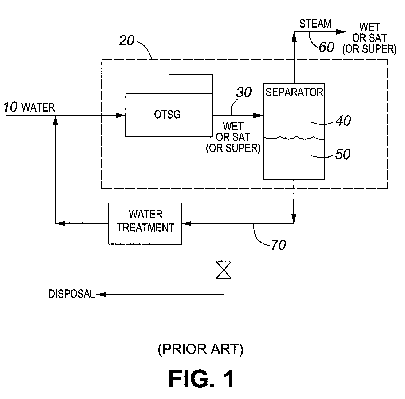
[0029]Referring to FIG. 1, a water source 10 for example, water produced from in situ recovery operations is provided to a once-through steam generator (OTSG) 20 and OTSG 20 produces a wet steam output 30. A steam separator 40 separates any boiler blowdown (boiler blowdown) 50 and a substantially saturated steam supply 60 is provided for use. A boiler blowdown stream 70, carrying contaminants, is sent to disposal or water treatment.

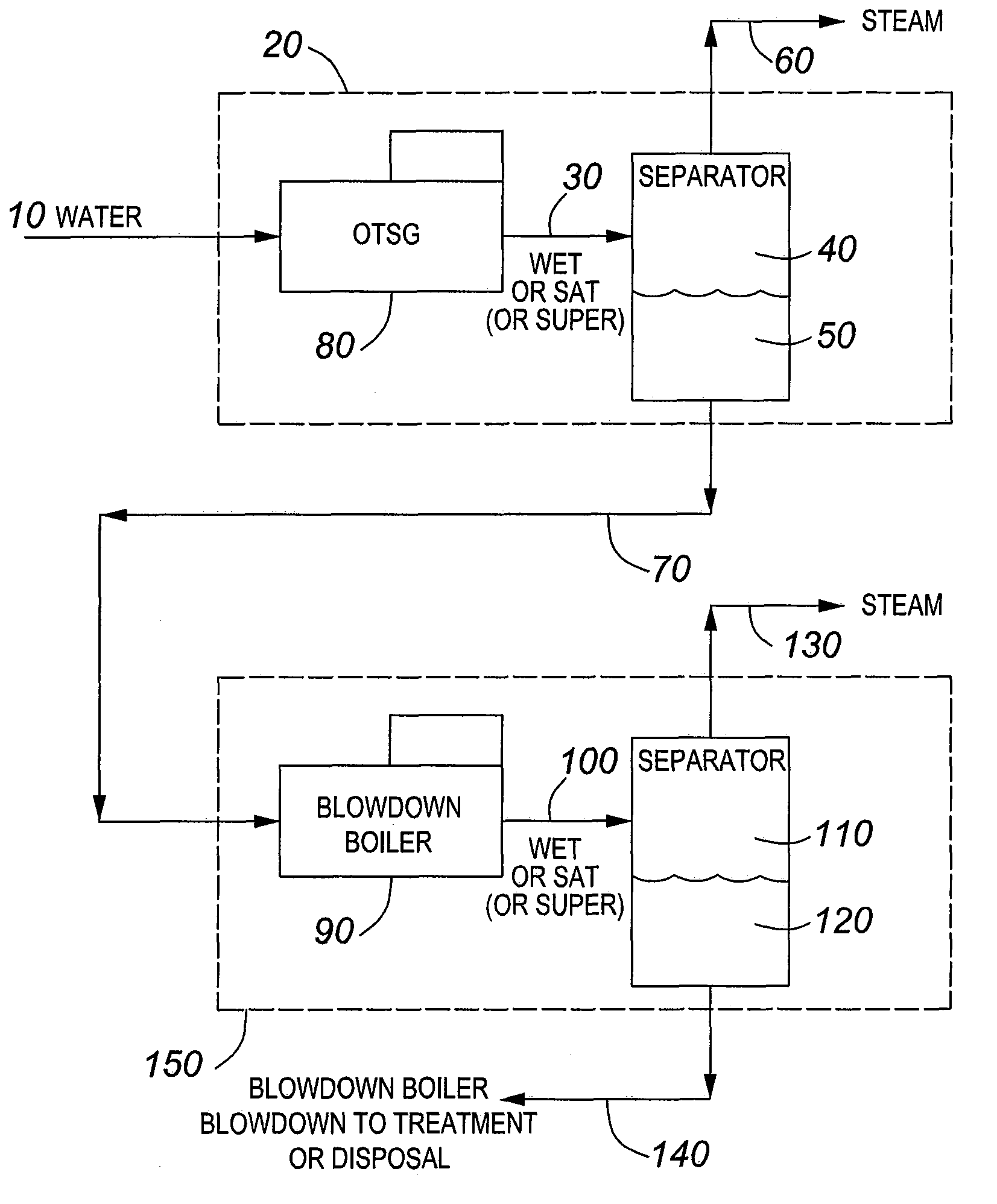
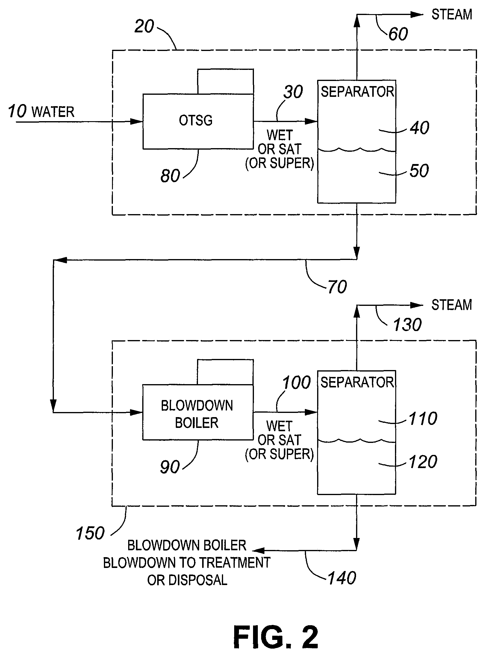
[0030]Referring to FIG. 2, a once-through steam generator 20 produces a wet steam output 30. A steam separator 40 separates boiler blowdown 50 and a substantially saturated steam supply 60 is provided for use. A boiler blowdown stream 70 carrying boiler blowdown 50 is provided to a blowdown boiler 90 which produces a wet blowdown steam output 100. The boiler blowdown 50 is delivered to the blowdown boiler 90 in an untreated state. As an example, the boiler...


PUM


Abstract

A method, apparatus, and system and operation of surface equipment to generate steam while reducing the quantity of boiler blowdown and thereby increasing the amount of feedwater that is re-used or re-cycled in generating said steam. The present invention teaches that, on a sustained basis, the blowdown stream at the outlet of a once-through steam generator can be routed to the inlet of a second once-through steam generator that is in series with the first, that blowdown stream can be used to generate additional steam in the second once-through steam generator and further reduce the amount of blowdown, and that this can be accomplished without need of any treatment that reduces hardness or silica levels of the blowdown stream prior to its entering or during its entry into the inlet of the second once-through steam generator. The output of this second steam generator is a substantially dry saturated steam vapor stream and, complementarily, a blowdown stream whose mass rate has been reduced substantially from that of the blowdown stream exiting the first steam generator.

Description

CROSS-REFERENCE TO RELATED APPLICATIONS[0001]This application claims priority to and full benefit of U.S. provisional patent application No. 60 / 983,003, filed Oct. 26, 2007, the entirety of which is incorporated by reference herein.FIELD OF THE INVENTION[0002]The present invention relates generally to a method and apparatus for steam generation. More particularly, the present invention relates to a method and apparatus for reducing the amount of boiler blowdown that requires treatment and / or disposal.BACKGROUND OF THE INVENTION[0003]In this description, reference to steam-based thermal recovery operations or processes indicates that steam injection into a hydrocarbon reservoir is either an exclusive or a nonexclusive aspect of the injection portion of the process. When steam is a non-exclusive aspect of the recovery process, this implies that other substances may be co-injected or injected sequentially with the steam. Thus, by way of example, steam-based thermal recovery operations ...

Claims


Application Information

Patent Timeline
Patent Type & Authority Patents(United States)
IPC IPC(8): F22D5/36
CPCF22B29/06
Inventor SUGGETT, JACK C.WASYLYK, MICHAEL J.
Owner FCCL PARTNERSHIP
Why Eureka
Try Eureka