Metal part and method of manufacturing metal part

a metal part and metal technology, applied in the direction of machines/engines, liquid fuel engines, cell components, etc., can solve the problem of wear on the face of the anodic oxide film on the rotor shaft, and achieve the effect of improving the surface smoothness

Active Publication Date: 2012-05-08
JTEKT CORP
View PDF12 Cites 1 Cited by
  • Summary
  • Abstract
  • Description
  • Claims
  • Application Information

AI Technical Summary

Benefits of technology

[0007]An object of the present invention provides a metal part made of an aluminum alloy, such as high-silicon aluminum alloy, that exhibits improved surface smoothness, and a method of manufacturing the metal part.
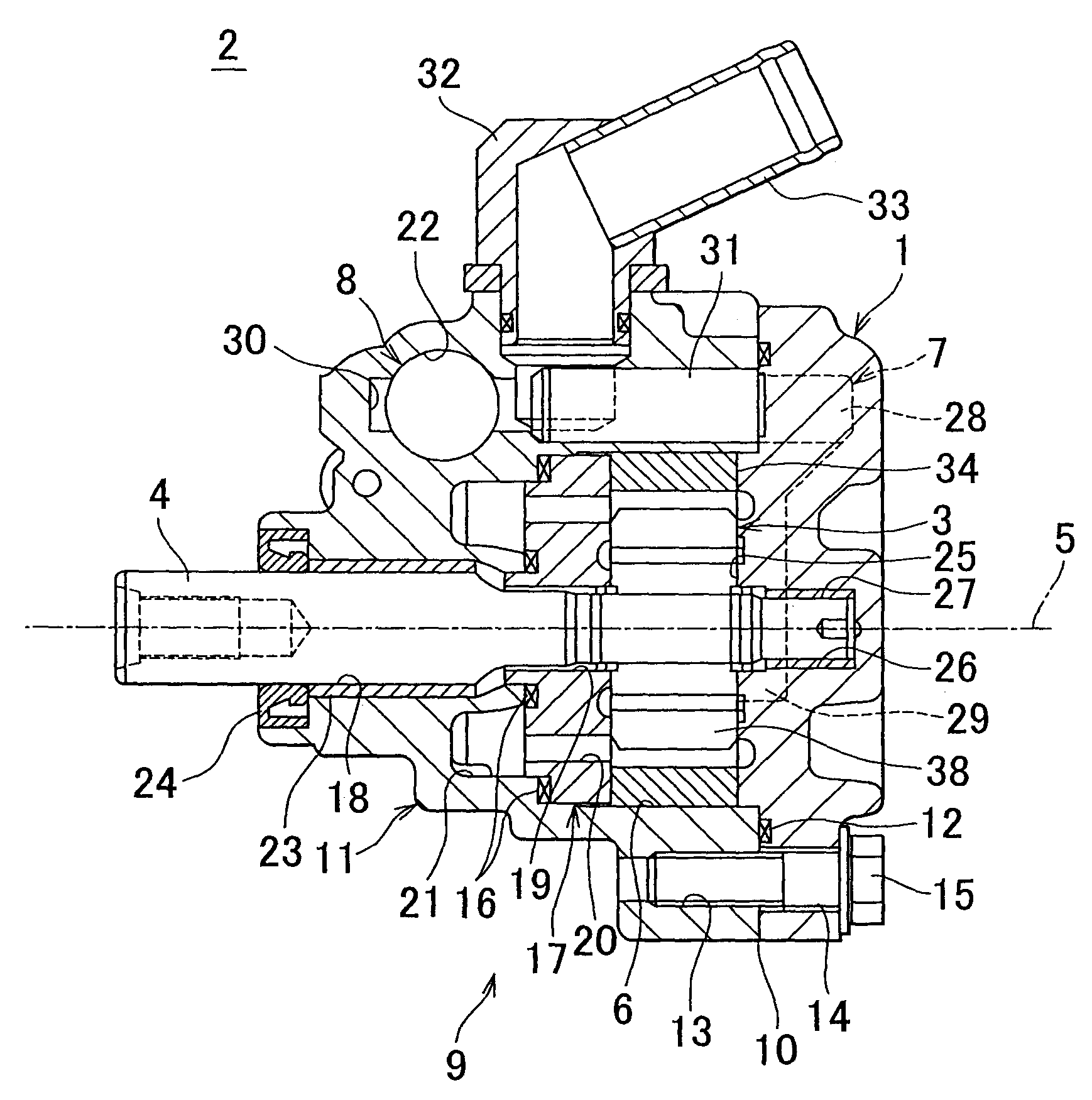
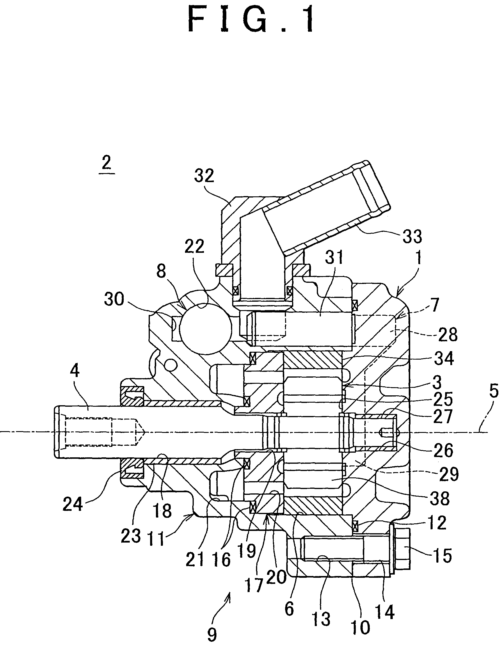
[0008]In order to improve the strength of a rear housing and thereby prevent deformation thereof in response to an increase in pressure within an oil pump (e.g., 8 MPa to 15 MPa), the rear housing may be formed of a high-silicon aluminum alloy that contains approximately 1 to 25% by mass of silicon (Si). In this case, however, the surface smoothness of an anodic oxide film that is formed on the surface of the rear housing deteriorates, thereby causing wear on one end of a rotor shaft that the anodic oxide film faces.
[0009]More specifically, due to high a concentration of silicon in the high-silicon aluminum alloy, solid-phase separation of silicon is accelerated during a cool down period, thereby producing a crystalline structure in which a silicon phase is deposited over a continuous phase formed by either an aluminum phase or a eutectic phase of aluminum and silicon. Consequently, the surface of the base material presents a state that the silicon phase is exposed in a dotted manner in the continuous phase.
[0013]In other words, the gradual increase of the current density at the above rate can prevent rapid growth of the anodic oxide film in the continuous phase and reduce the difference in thickness of the anodic oxide film between the both regions by letting the anodic oxide film enter the silicon phase region at the early stage. After a surface of the silicon phase is completely coated with the anodic oxide film, anodization is continued at the constant current density by constant current control. Thus, it is possible to coat the whole surface of the base material with the anodic oxide film in nearly equal thickness with excellent surface smoothness.
[0015]According to the above manufacturing method, as a rate of increase in the current density is reduced, uniform thickness of the anodic oxide film can be achieved, and the surface of the anodic oxide film can be smoothed. However, productivity of the metal part having the anodic oxide film tends to decline when the rate of increase in the current density is reduced. It is because a prolonged process is required to form the anodic oxide film in prescribed thickness.
[0016]Given that the above metal part having the anodic oxide film with excellent surface smoothness and the like is manufactured while the productivity of the metal part is maintained, the rate of increase in the current density may be at least 0.15 A / dm2 per minute within the above range. In addition, the current density may be maintained at a prescribed value between 0.8 A / dm2 and 1.2 A / dm2 inclusive. When the current density falls below the above ranges, the prolonged process is required to form the anodic oxide film in the prescribed thickness. Consequently, the productivity of the metal part having the anodic oxide film may decline. Meanwhile, when the current density exceeds the above ranges, the anodic oxide film increases roughness on its surface, and thus wear resistance of the anodic oxide film might be lowered.

Problems solved by technology

In this case, however, the surface smoothness of an anodic oxide film that is formed on the surface of the rear housing deteriorates, thereby causing wear on one end of a rotor shaft that the anodic oxide film faces.

Method used


Image

  • Metal part and method of manufacturing metal part
  • Metal part and method of manufacturing metal part
  • Metal part and method of manufacturing metal part

Examples


example 1

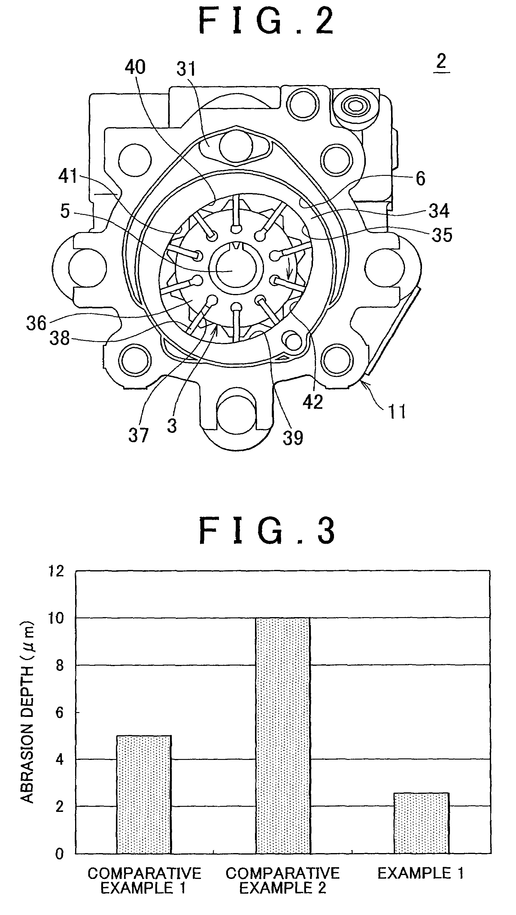
[0053]As a base material, a flat plate member (25 mm in height×25 mm in width×5 mm in thickness) that is made of high-silicon aluminum alloy with 14% by mass of silicon was prepared. High-silicon aluminum alloy that constitutes the plate member had a hardness of HV 150 at a depth of 1 mm from the surface with Vickers hardness scale HV 0.01. Ten point height of roughness profile RZJIS94 on the surface of the plate member was set to be 1 μm.

[0054]The plate member was degreased in advance, connected to an anode of a power supply device, and immersed in a sulfate bath together with a graphite cathode. A current density of current provided to both the anode and the cathode started at 0 A / dm2 in the first process and was increased for 3 minutes at a rate of 0.333 A / dm2 per minute to reach 1 A / dm2. Next, once the current density reached a prescribed current density in the first process, the current density was further maintained for 37 minutes, that is, a total of 40 minutes for anodizatio...

example 2

[0055]A metal part having a surface coated with an anodic oxide film was manufactured in the same manner as Example 1 except that the current density of the current provided to both the anode and the cathode started at 0 A / dm2 in the first process and was increased for 6 minutes at a rate of 0.167 A / dm2 per minute to reach 1 A / dm2 and that the current density was further maintained for 34 minutes, that is, a total of 40 minutes for anodization.


PUM

PropertyMeasurementUnit
current densityaaaaaaaaaa

Abstract

A metal part in which a base material of silicon-aluminum alloy having 1 to 25% by mass of silicon as an anode is immersed in an electrolyte together with a cathode, and at least a portion of a surface of the base material is anodized and coated with an anodic oxide film. A current density provided to both the anode and the cathode is increased from an initial current density of 0 A / dm2 at a rate between 0.15 and 0.35 A / dm2 per minute, wherein once the current density reaches a prescribed current density of between 0.8 A / dm2 and 1.2 A / dm2, the current density provided to the anode and the cathode is maintained at the prescribed current density.

Description

INCORPORATION BY REFERENCE[0001]The disclosure of Japanese Patent Application No. 2008-149454 filed on Jun. 6, 2008 and Japanese Patent Application No. 2008-151884 filed on Jun. 10, 2008 including the specification, drawings and abstract is incorporated herein by reference in its entirety.BACKGROUND OF THE INVENTION[0002]1. Field of the Invention[0003]The present invention relates to a metal part in which at least a portion of the surface of an aluminum alloy base material is coated with an anodic oxide film, and also relates to a method of manufacturing the metal part.[0004]2. Description of the Related Art[0005]In an automobile, for example, an oil pump is used to circulate oil in an engine and a hydraulic power train. The oil pump includes: a working chamber; a housing that has an intake passage and a discharge passage, both of which communicate with the working chamber, and that is configured by a plurality of housing pieces; and a rotor, disposed in the working chamber, that ro...

Claims


Application Information

Patent Timeline
Patent Type & Authority Patents(United States)
IPC IPC(8): F01C21/10F03C4/00F04C2/00F03C2/00
CPCC25D11/04F04C2/3441F04C14/226C25D11/024F04C2230/91
Inventor SAITO, TOSHIYUKIMIO, TAKUMINISHI, KOJIFUKAMI, HAJIMEETO, ATSUSHIYAO, HIROYUKI
Owner JTEKT CORP
Why Eureka
Try Eureka