Micromechanical component having multiple caverns, and manufacturing method

a micromechanical component and manufacturing method technology, applied in the direction of fluid speed measurement, instrumentation, and mechanical device details, can solve the problems of monolithic micromechanical sensors and the associated evaluation circui

Inactive Publication Date: 2012-05-08
ROBERT BOSCH GMBH
View PDF17 Cites 2 Cited by
  • Summary
  • Abstract
  • Description
  • Claims
  • Application Information

AI Technical Summary

Benefits of technology

[0003]The micromechanical component according to the present invention has at least two caverns having different internal pressures. This advantageously makes possible the integration of multiple different micromechanical sensors, having different internal atmospheric pressures as determined by their design, into one common micromechanical component. In a micromechanical acceleration sensor the internal atmospheric pressure in the cavern is specified, for example, as 5 mbar to 1.5 bar. With this pressure, a suitable damping for the micromechanical deflection part of acceleration sensors can be established. For actively oscillating sensors, e.g., for rotation-rate sensors, the internal cavern pressure that is chosen should be very low in order to ensure high quality for the oscillator. Internal cavern pressures of <10−3 bar are advantageous here.
[0004]An advantageous example embodiment of the micromechanical component provides for at least two caverns to be delimited by one common cap. This makes possible a particularly compact construction for the micromechanical component. The number of steps for manufacturing such a component can moreover be reduced thereby. In particular, these two caverns have different internal atmospheric pressures.
[0005]It is also advantageous that at least one cavern has a closed-off access opening. A specifiable pressure in the cavern can easily be established by way of such an access opening.

Problems solved by technology

It is furthermore known to integrate micromechanical sensors and the associated evaluation circuit monolithically.

Method used


Image

  • Micromechanical component having multiple caverns, and manufacturing method
  • Micromechanical component having multiple caverns, and manufacturing method
  • Micromechanical component having multiple caverns, and manufacturing method

Examples


Embodiment Construction

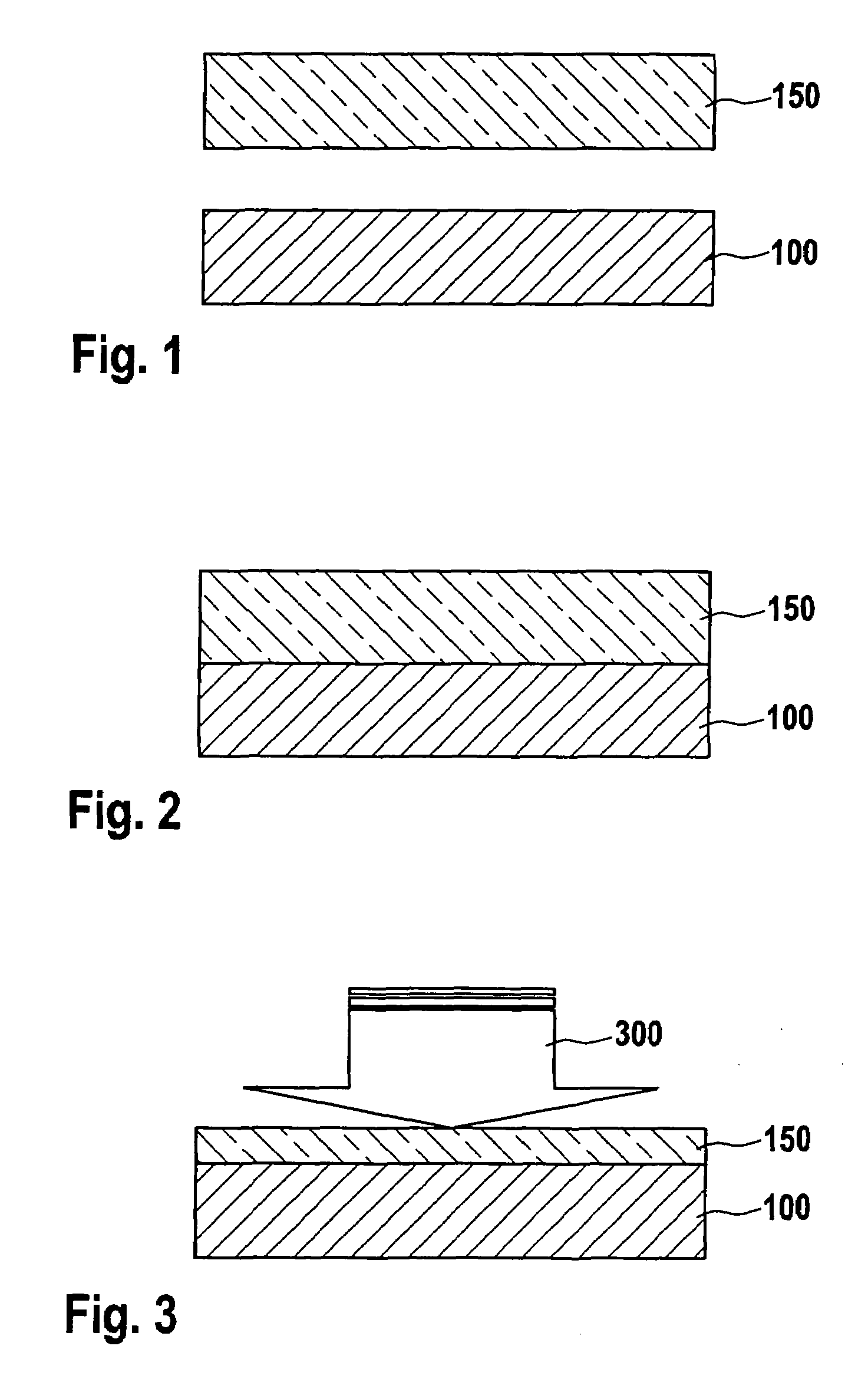
[0033]FIG. 1 shows the preparation of a substrate and a glass for the manufacture of a cap. A cap substrate 100, which in this example is made of silicon, is disposed and aligned with respect to a glass 150. Glass 150 is made of Pyrex in this example. For joining, cap substrate 100 and glass 150 must exhibit a suitable roughness on the surfaces facing one another.

[0034]FIG. 2 shows the joining of substrate 100 to glass 150. The joining is accomplished, for example, by way of the technique of anodic bonding.

[0035]FIG. 3 shows the thinning of the glass layer. Thinning action 300 of glass 150 is accomplished by grinding and chemical-mechanical polishing (CMP). The result is to produce, in this example, a glass layer 150 having a thickness of approx. 50 μm.

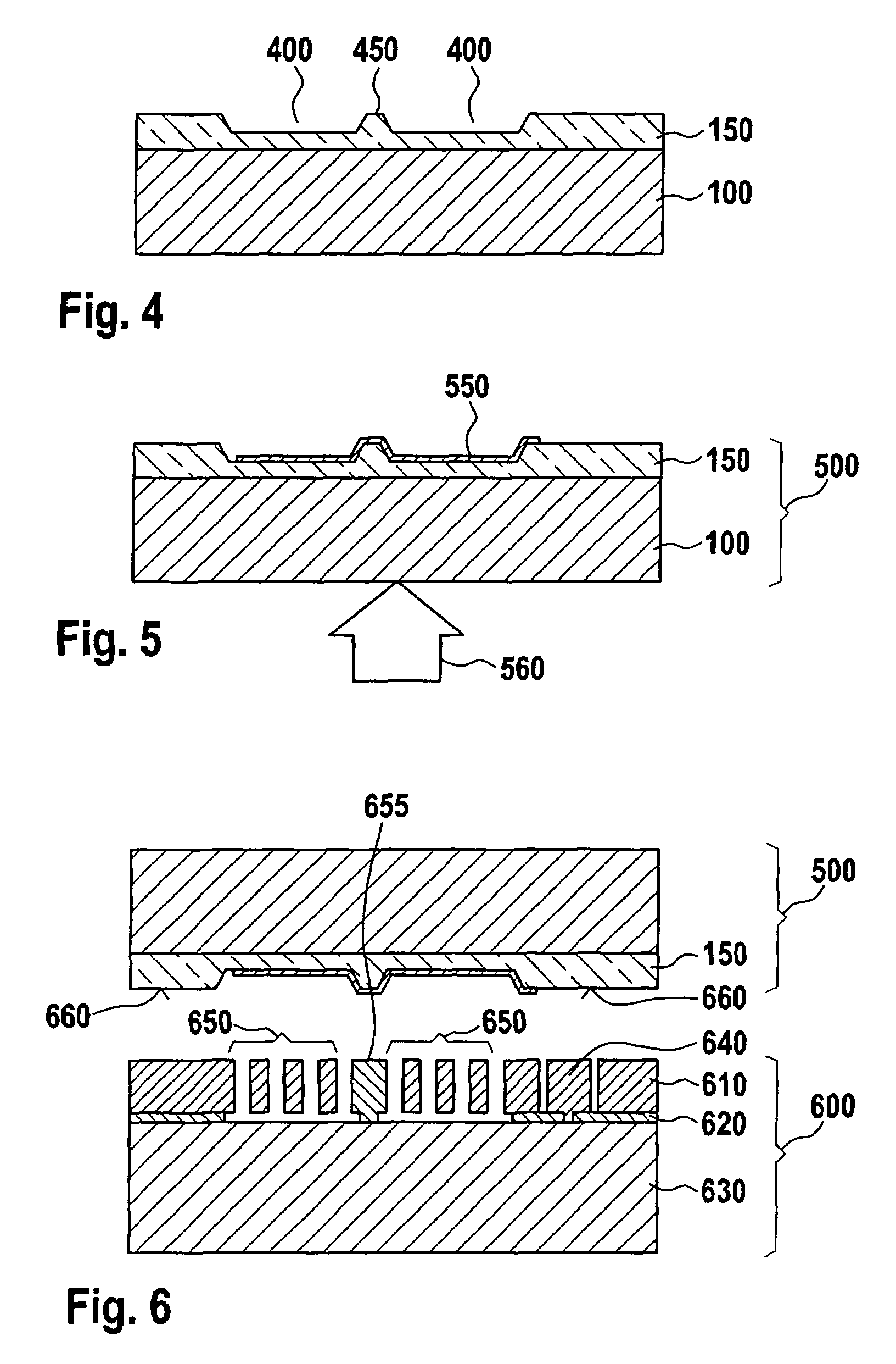
[0036]FIG. 4 shows the production of recesses in the glass. Recesses 400 in glass 150 can be produced, for example, by a buffered oxide etch (BOE) method. In the example shown, recesses 400 have a depth of approx. 5.5 μm. Provision ca...


PUM

PropertyMeasurementUnit
atmospheric pressureaaaaaaaaaa
pressureaaaaaaaaaa

Abstract

A micromechanical component having at least two caverns is provided, the caverns being delimited by the micromechanical component and a cap, and the caverns having different internal atmospheric pressures. The micromechanical component and cap are hermetically joined to one another at a first specifiable atmospheric pressure, then an access to at least one cavern is produced, and subsequently the access is hermetically closed off at a second specifiable atmospheric pressure.

Description

FIELD OF THE INVENTION[0001]The present invention relates to a micromechanical component, and a method for manufacturing a micromechanical component.BACKGROUND INFORMATION[0002]It is known from the existing art that discrete sensors, e.g., rotation-rate sensors and acceleration sensors, can be manufactured micromechanically. It is likewise known that rotation-rate and acceleration sensors can be integrated in a common housing, together with one or more evaluation circuits, to constitute a sensor system. It is furthermore known to integrate micromechanical sensors and the associated evaluation circuit monolithically. Published German patent document DE 101 04 868 describes the packaging of a micromechanical sensor by way of a cap. The sensor and cap are anodically bonded, and delimit a cavern. It is furthermore described in published German patent document DE 102 43 014 to dispose two caverns in one micromechanical component.SUMMARY[0003]The micromechanical component according to the...

Claims


Application Information

Patent Timeline
Patent Type & Authority Patents(United States)
IPC IPC(8): H01L27/14B81B7/00B81C1/00
CPCB81B7/0041B81B7/02B81B2201/025B81C2201/019B81C2203/0145
Inventor FISCHER, FRANKGRAF, ECKHARDSTAHL, HEIKOKUEPPERS, HARTMUTSCHEUERER, ROLAND
Owner ROBERT BOSCH GMBH
Why Eureka
Try Eureka