Focal position determining method, focal position determining apparatus, feeble light detecting apparatus and feeble light detecting method
a technology of focal position and determining apparatus, which is applied in the direction of optical radiation measurement, camera focusing arrangement, printers, etc., can solve the problems that the luminescence of biological specimens cannot be directly confirmed with naked eyes in most cases, and it is difficult to bring a lens into focus on the specific region of the specimen with naked eyes
- Summary
- Abstract
- Description
- Claims
- Application Information
AI Technical Summary
Benefits of technology
Problems solved by technology
Method used
Image
Examples
third embodiment
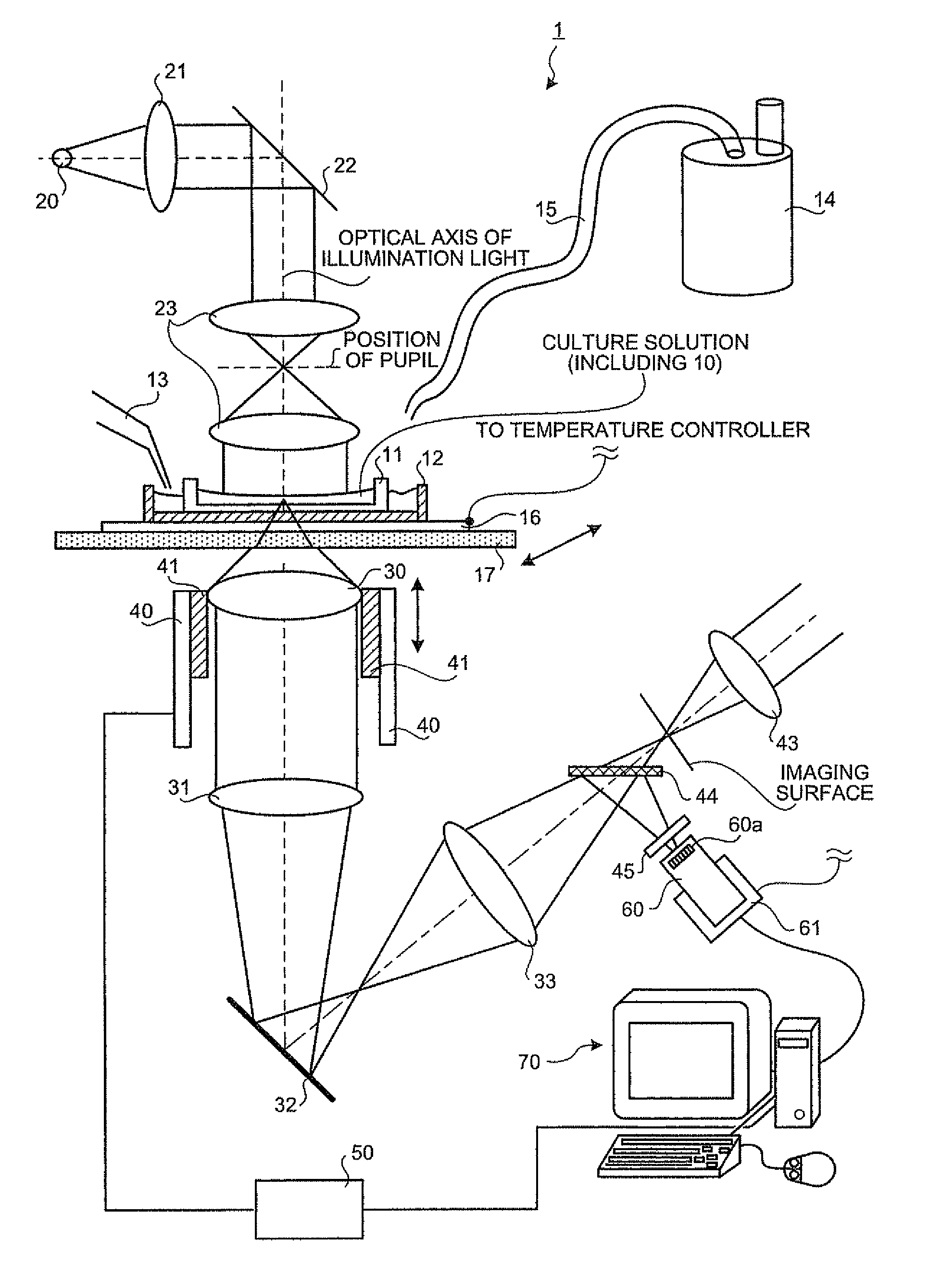
[0192]Next, the outline, structure and process of a focal position determining apparatus 1′ according to the third embodiment of the present invention will be explained in detail with reference to the drawings. The parts overlapped with those in the first and second embodiments may sometimes be omitted.
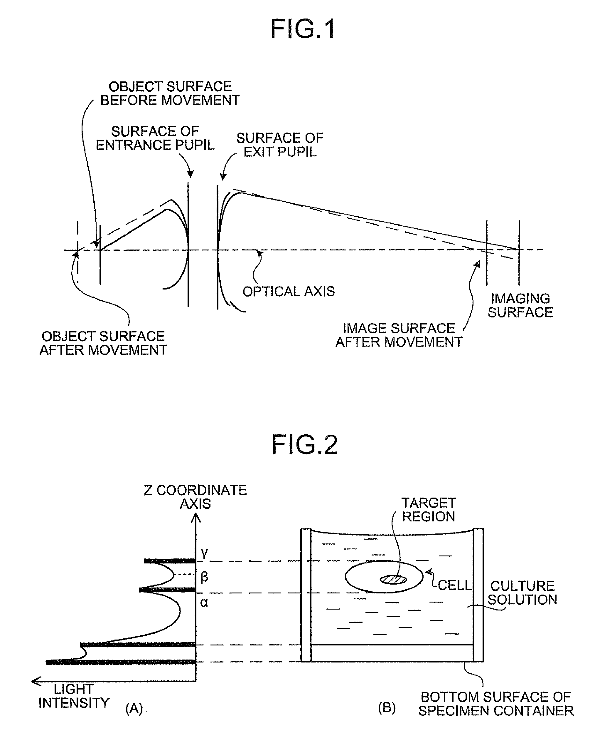
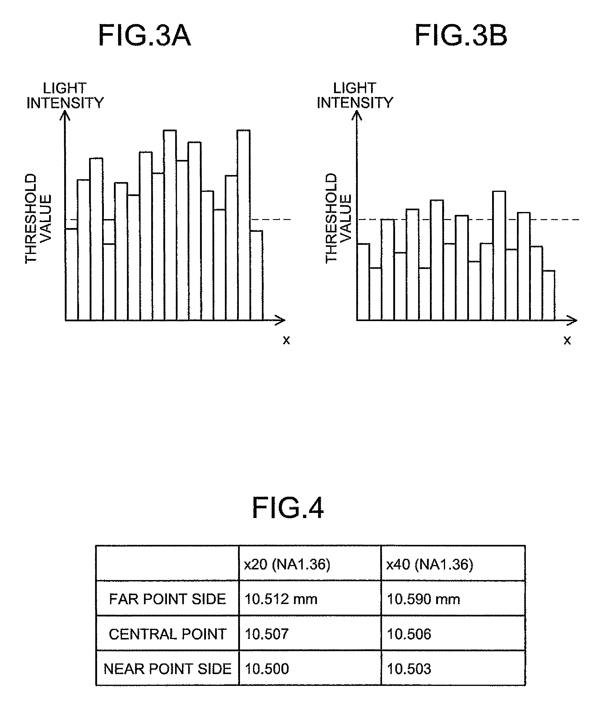
[0193]Firstly, the outline of the present invention will be explained. The present invention images a specimen (specifically, a biological specimen containing a luminescent material) while moving an objective lens, and measures the focal position of the objective lens. Then, a contrast, which is a difference between the maximum value and the minimum value of pixel values of each pixel composing the image, is calculated based on the imaged image. Then, the focal position of the objective lens focused on the observed target region is determined based on the calculated contrast and the measured focal position of the objective lens. Specifically, in the present invention, the contrast of ...
first embodiment
[0270]The structure of the first embodiment will be explained with reference to FIGS. 36 and 37. FIG. 36 is a schematic view of a feeble light detecting apparatus with an inverted microscope as a base. The feeble light detecting apparatus includes a light source A2, an illumination optical system A1 that makes the light emitted from the light source A2 into parallel light and directs the parallel light to a test specimen A4, an observation optical system A5 for forming an image of the test specimen A4, an ocular lens A1 for magnifying the image of the test specimen A4 to be visually observed, and a CCD camera A8 having an imaging device A7 for imaging the image of the test specimen A4. A computer A16 that also serves as a television monitor is connected to the CCD camera A8 via a signal cable A100.
[0271]The illumination optical system A1 includes, in this order from the light source A2, a collector lens A10, a deflection mirror A12 for deflecting an optical axis A11 of the illuminat...
second embodiment
Simultaneous Measurement of Fluorescence and Bioluminescence
[0290]An optical system of a feeble light detecting apparatus that can simultaneously execute digital zooming and optical zooming and simultaneously measure fluorescence and bioluminescence is schematically shown in FIG. 41. The structure and the operation of the optical system are basically the same as those explained in the first embodiment in FIG. 36 except that an exciting optical system A49 is added. The optical system basically has a structure with an inverted optical microscope as a base. It includes an illumination light source, specimen stage, objective lens, and computer. The optical system is composed of an illumination optical system A1 for guiding light to the test object A4 in the specimen container A21 such as the petri dish, and an observation optical system A5 for guiding the feeble light emitted from the test object A4 to the CCD camera A8.
[0291]The exciting optical system A49 includes an exciting light so...
PUM
 Abstract
Description
Claims
Application Information
 - R&D
- Intellectual Property
- Life Sciences
- Materials
- Tech Scout
- Unparalleled Data Quality
- Higher Quality Content
- 60% Fewer Hallucinations
Browse by: Latest US Patents, China's latest patents, Technical Efficacy Thesaurus, Application Domain, Technology Topic, Popular Technical Reports.
© 2025 PatSnap. All rights reserved.Legal|Privacy policy|Modern Slavery Act Transparency Statement|Sitemap|About US| Contact US: help@patsnap.com


