Computer-based computational tools for use in electrophysiology

a computer-based, electrophysiological technology, applied in the field of electrophysiology, can solve the problems of many fundamental phenomena that have been poorly understood or not understood at all, and achieve the effect of limiting the scope of invention

Active Publication Date: 2012-05-15
KLEE MAURICE M
View PDF5 Cites 15 Cited by
  • Summary
  • Abstract
  • Description
  • Claims
  • Application Information

AI Technical Summary

Benefits of technology

[0045]The reference numbers and figure number used in the above summaries of the various aspects of the invention are only for the convenience of the reader and are not intended to and should not be interpreted as limiting the scope of the invention. More generally, it is to be understood that both the foregoing general description and the following detailed description are merely exemplary of the invention and are intended to provide an overview or framework for understanding the nature and character of the invention.

Problems solved by technology

As a consequence many fundamental phenomena have been poorly understood or not understood at all.

Method used


Image

  • Computer-based computational tools for use in electrophysiology
  • Computer-based computational tools for use in electrophysiology
  • Computer-based computational tools for use in electrophysiology

Examples


example 1

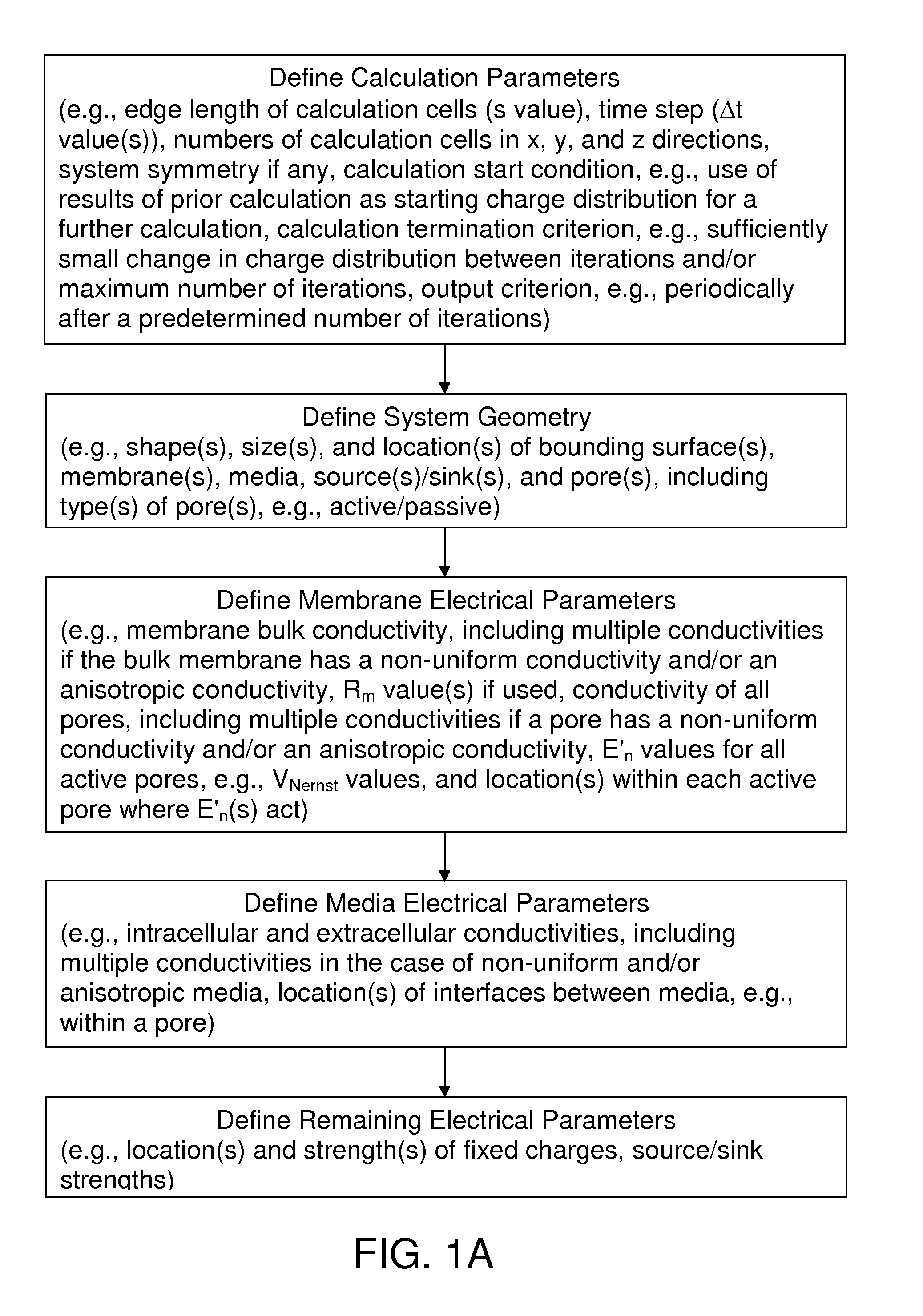
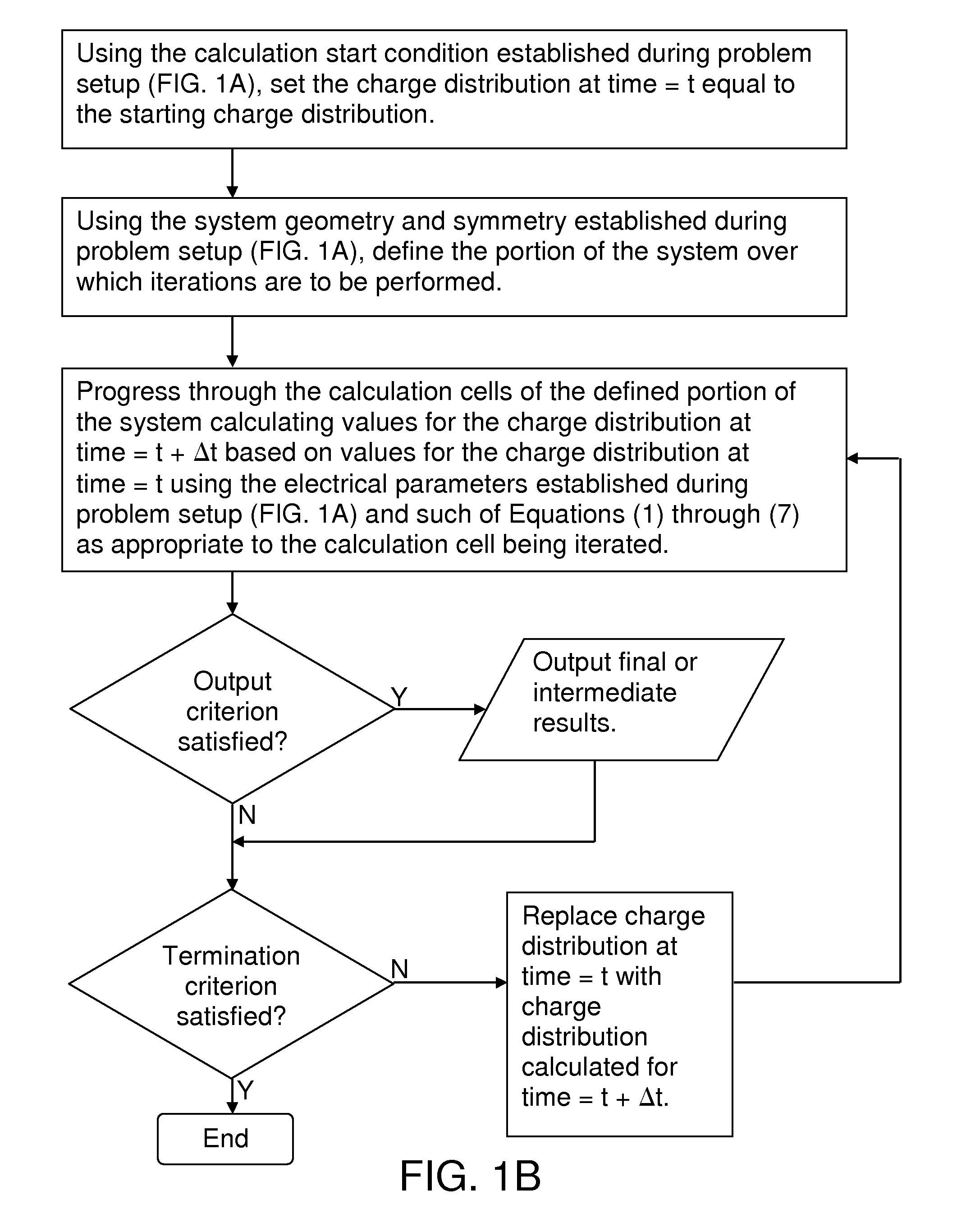
[0147]This example illustrates the use of the computer-based computational tools of the invention to determine charge distributions that cause current to enter a pore in a biological membrane.

[0148]The example demonstrates that: (1) the opening of a biological pore produces an initial rapid redistribution of charge in the vicinity of the pore followed by a slower steady decay of the overall charge distributions on either side of the membrane (i.e., the opening of a pore involves multiple time constants having substantially different values); and (2) as shown in FIG. 5, during the initial rapid phase, charges accumulate at the entrance and exit ends of the pore which have a sign opposite to that of the charges on the surrounding membrane surface (referred to herein as “current-turning charges”).

[0149]Analogies to these current-turning charges can be found in the charge distributions postulated to exist in natural pores. In particular, FIGS. 11.11 and 17.3 of Hille (2001) show renditi...

example 2

[0167]This example illustrates the use of Equations (1)-(2) and (4)-(6) to calculate a charge distribution produced by an active pore.

[0168]FIG. 11 shows the system that was analyzed. A square patch of a planar membrane having an area of 140 Å×140 Å, a thickness of 80 Å, and zero conductivity was placed between two 20 Å layers of a biological fluid having a conductivity of 4 siemens / meter (resistivity=25 ohm-cm). The membrane patch was assumed to include a low resistance path at its outer edge (the “perimeter path”) having a thickness of 4 Å.

[0169]The active pore was a square having 20 Å sides located at the center of the planar membrane. The conductivity of the fluid filling the pore was the same as that of the surrounding media, i.e., 4 siemens / meter. The media were assumed to have different ionic compositions and the pore was assumed to be ion selective so as to generate a Nernst potential of −100 millivolts (intracellular minus extracellular).

[0170]The interface between the extr...

example 3

[0181]This example illustrates the use of Equations (1) and (2) to calculate a charge distribution associated with a difference in conductivity between the media on the intracellular and extracellular sides of a passive pore. It also illustrates the application of an applied current to a pore.

[0182]FIG. 17 shows the system that was analyzed. A square patch of a planar membrane having an area of 140 Å×140 Å, a thickness of 80 Å, and zero conductivity was placed between two 20 Å layers of biological fluid which in the initial analysis had equal conductivities of 0.727 siemens / meter (resistivity=137.5 ohm-cm). The pore was a square having 20 Å sides located at the center of the planar membrane. In the initial analysis, the conductivity of the fluid filling the pore was the same as that of the surrounding media, i.e., 0.727 siemens / meter.

[0183]The overall volume was divided into 35×35×30 calculation cells having an edge length (s value) of 4 Å. A time step (Δt) of 1 picosecond was used ...


PUM


Abstract

Computer-based computational tools for use in determining spatial charge distributions for biological systems that include one or more biological membranes are provided. At least one of the biological membrane includes at least two regions having different electrical properties, e.g., the biological membrane can include a pore having a higher conductivity than the surrounding bulk membrane. In other cases, the membrane can include non-active and active regions, with conservative fields acting at the non-active regions and a combination of conservative and non-conservative fields acting at the active regions. The non-conservative fields can, for example, originate from differences in ionic concentrations of the type which generate Nernst potential differences across membranes. Using the computer-based computational tools, charge distributions not previously known to exist have been discovered, e.g., ring-shaped charge distributions in the vicinity of an active pore.

Description

[0001]This application claims the benefit under 35 USC §119(e) of U.S. Provisional Application No. 61 / 036,100 filed Mar. 13, 2008, and U.S. Provisional Application No. 61 / 088,676 filed Aug. 13, 2008, the contents of each of which is hereby incorporated herein by reference in its entirety.[0002]The text and drawings of the disclosure of this patent document contain material which is subject to copyright protection. The copyright owner has no objection to the facsimile reproduction by anyone of the patent document or the patent disclosure, as it appears in the Patent and Trademark Office patent file or records, but reserves all other copyright rights whatsoever.I. FIELD OF THE INVENTION[0003]This invention relates to electrophysiology and, in particular, to computer-based computational tools for analyzing and interpreting electrophysiological data, designing electrophysiological experiments, and discovering heretofore unknown mechanisms and phenomena of electrophysiological systems.II...

Claims


Application Information

Patent Timeline
Patent Type & Authority Patents(United States)
IPC IPC(8): G06G7/62
CPCG06F19/704G01N27/00G16C20/30G06F30/20
Inventor KLEE, MAURICE M.
Owner KLEE MAURICE M
Why Eureka
Try Eureka