Piezoelectric porcelain composition, and piezoelectric ceramic electronic component

a technology of piezoelectric ceramic and composition, which is applied in the direction of basic electric elements, electric devices, generators/motors, etc., can solve the problems of insufficient reliability, ag—pd alloy is relatively expensive, and the cost of internal electrode materials is occupied by the bulk of material costs, etc., to achieve excellent piezoelectric characteristics, excellent piezoelectric characteristics, and improved sintering degree in a reductive atmosphere

Active Publication Date: 2012-05-22
MURATA MFG CO LTD
View PDF11 Cites 3 Cited by
  • Summary
  • Abstract
  • Description
  • Claims
  • Application Information

AI Technical Summary

Benefits of technology

[0025]According to the piezoelectric porcelain composition of the present invention, since the degree of sintering in a reductive atmosphere can be improved, desired and excellent piezoelectric characteristics can be obtained without leading to a sintering defect even when co-sintering with an internal electrode material mainly including Ni is conducted in a reductive atmosphere.
[0026]According to the piezoelectric ceramic electronic component of the present invention in which an external electrode is formed on a surface of a piezoelectric ceramic base, the piezoelectric ceramic base is formed by the piezoelectric porcelain composition, so that excellent piezoelectric characteristics can be obtained even when sintering is conducted in a reductive atmosphere.
[0027]According to the piezoelectric ceramic electronic component of the present invention including a piezoelectric ceramic base made up of an internal electrode and a piezoelectric ceramic layer alternately laminated and sintered, and in which an external electrode is formed on the surface of the piezoelectric ceramic base, the piezoelectric ceramic layer is formed of the piezoelectric porcelain composition, so that sintering using a material mainly including Ni as an internal electrode material is enabled, and a piezoelectric ceramic electronic component having excellent piezoelectric characteristics like low migratory property and practical value can be obtained at a low cost.BRIEF EXPLANATION OF DRAWINGS
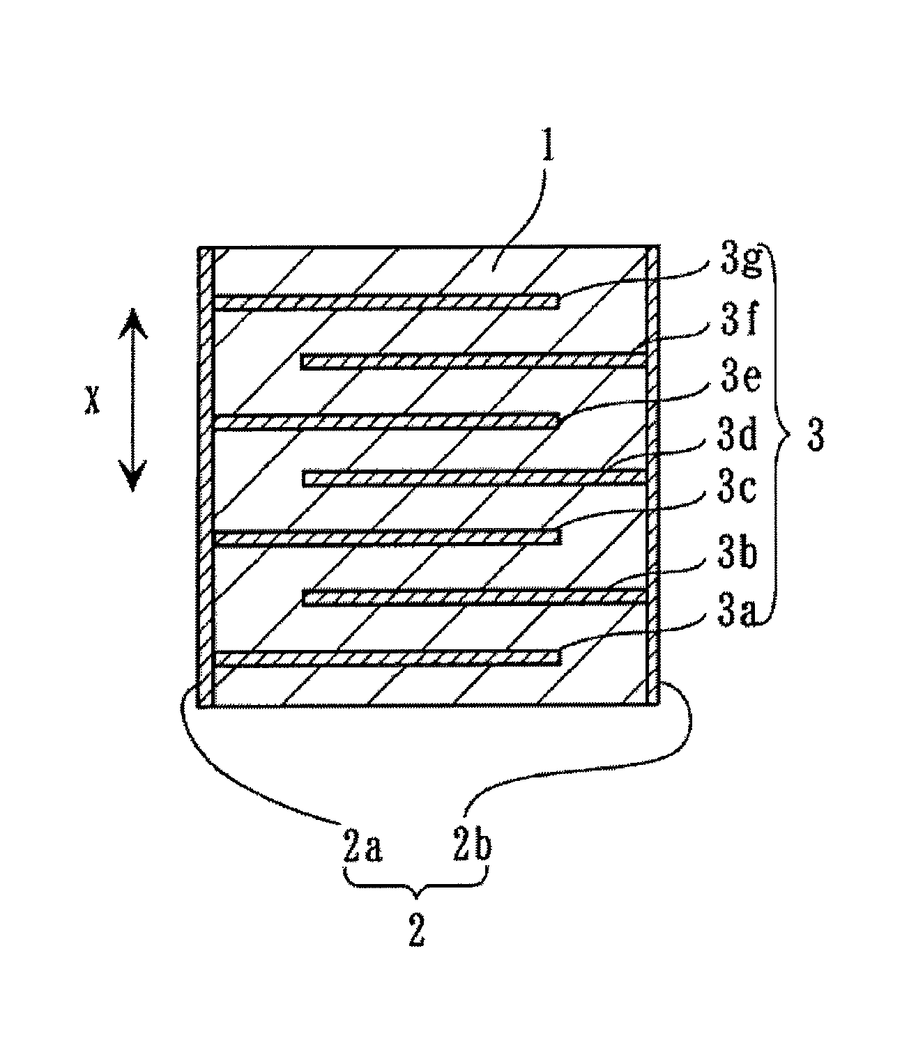
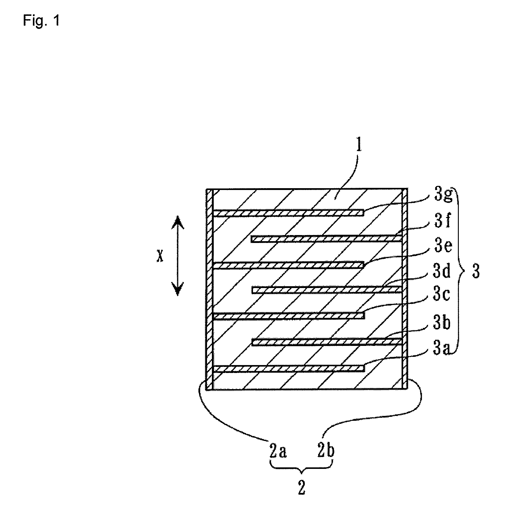
[0028]FIG. 1 is a cross sectional view showing one exemplary embodiment of a laminated piezoelectric actuator embodying a piezoelectric ceramic electronic component of the present invention.
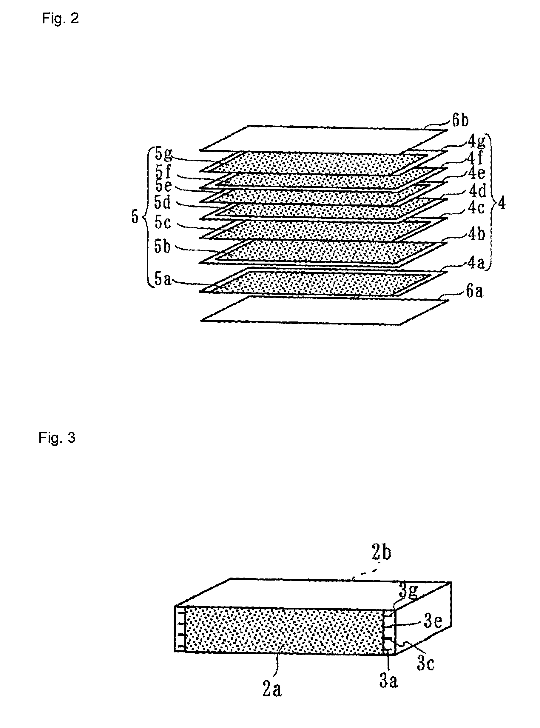
[0029]FIG. 2 is a perspective view of a ceramic green sheet obtained in the course of production of the piezoelectric actuator.
[0030]FIG. 3 is a perspective view of the piezoelectric actuator.DESCRIPTION OF REFERENCE SYMBOLS

Problems solved by technology

As an internal electrode material, conventionally, an Ag—Pd alloy is widely used, but the Ag—Pd alloy is relatively expensive so that most of the material cost is occupied by the internal electrode material.
Also there is a drawback that sufficient reliability will not be ensured because of occurrence of migration of Ag at the time of driving the component by a low frequency area or DC voltage.
As such a low-migratory material, Pd, Pt, Ni and the like are known, but precious metal materials such as Pd and Pt are expensive, and may result in further rising in the material cost.

Method used


Image

  • Piezoelectric porcelain composition, and piezoelectric ceramic electronic component
  • Piezoelectric porcelain composition, and piezoelectric ceramic electronic component
  • Piezoelectric porcelain composition, and piezoelectric ceramic electronic component

Examples


example 1

[0085]In Example 1, samples in containing different amounts of Mn and the specific tetravalent element M4, relative to the main ingredient were prepared, and their characteristics were evaluated.

[0086]First, as a ceramic base material, K2CO3, Na2CO3, Li2CO3, Nb2O5, CaCO3, SrCO3, BCO3, ZrO2, SnO2, HfO2, MnO, and Yb2O3 were prepared. Then weighing was conducted to achieve compositions having M2, M4, α, β and δ as shown in Table 1 in the general formula [100{0.96(K0.44Na0.54Li0.02)NbO3−0.04M2M4O3}+αMn+βM4+δYb]. Then these weighed objects were put into a ball mill containing PSZ balls, and wet-mixed for about 90 hours in ethanol as a solvent. The obtained mixture was dried, and calcinated at a temperature of 900° C. to obtain a calcinated object.

[0087]After breaking lumps of the calcinated object, the calcinated object was put into a ball mill together with a binder, a dispersing agent and pure water, and thoroughly wet-mixed, and then formed by a doctor blade method to obtain a ceramic...

example 2

[0114]In Example 2, samples having various molar ratios a, b, c and x in the main ingredient compositions were prepared and their characteristics were evaluated.

[0115]First, as a ceramic base material, K2CO3, Na2CO3, Li2CO3, Nb2O5, Ta2O5, CaCO3, ZrO2, MnO and Yb2O3 were prepared. Then weighing was conducted to achieve compositions having a, b, c and x as shown in Table 3 in the general formula [100{1−x(K1−a−bNaaLib)(Nb1−cTac)O3−xCaZrO3}+αMn+βZr+0.5Yb] (α is 5 or 2, and β is 3.0 or 1.0).

[0116]Then samples of Sample Nos. 41 to 52 were prepared in a similar manner and procedure as in Example 1.

[0117]Next, for each sample of Sample Nos. 41 to 52, the logarithm of an insulation resistance log(ρ / Ω·cm) was measured by using a DC voltmeter, and then an electric field of 3.0 kV / mm was applied for 30 minutes in insulating oil at 80° C. to effect a polarization treatment.

[0118]Next, for each sample, dielectric loss tan δ, dielectric constant εr, electromechanical coupling coefficient kp of rad...

example 3

[0128]In Example 3, samples and containing Ni in addition to the composition of Sample Nos. 27 in Example 1 and having various contents of Ni were prepared, and characteristics of these samples were evaluated.

[0129]First, as a ceramic base material, K2CO3, Na2CO3, Li2CO3, Nb2O5, Ta2O5, CaCO3, ZrO2, MnO and NiO were prepared. Then weighing was conducted so that γ has the composition as shown in Table 5 in the general formula [100{0.96(K0.44Na0.54Li0.02)NbO3−0.04CaZrO3}+5Mn+1.0Zr+γNi].

[0130]Then samples of Sample Nos. 61 to 64 were prepared in a similar manner and procedure as in Example 1.

[0131]Next, for each sample of Sample Nos. 61 to 64, the logarithm of an insulation resistance log(ρ / Ω·cm) was measured by using a DC voltmeter, and then an electric field of 3.0 kV / mm was applied for 30 minutes in insulating oil at 80° C. to effect a polarization treatment.

[0132]Next, for each sample, dielectric loss tan δ, dielectric constant εr, electromechanical coupling coefficient kp of radial...


PUM

PropertyMeasurementUnit
Curie point Tcaaaaaaaaaa
dielectric constant εraaaaaaaaaa

Abstract

A piezoelectric porcelain composition includes a main ingredient represented by a general formula ((1−x)(K1−a−bNaaLib) (Nb1−cTac)O3−xM2M4O3) (where M2 represents Ca, Ba or Sr, M4 represents Zr, Sn or Hf, and 0.005≦x≦0.1, 0≦a≦0.9, 0≦b≦0.1, 0≦a+b≦0.9, and 0≦c≦0.3), and Mn is contained in an amount ranging from 2 to 15 mol, relative to 100 mol of the main ingredient, and the M4 is contained in an amount ranging from 0.1 to 5.0 mol, relative to 100 mol of the main ingredient. Preferably, Ni is contained in an amount ranging from 0.1 to 5.0 mol, relative to 100 mol of the main ingredient, and also preferably Yb, In and the like specific rare earth elements is contained. A ceramic layer in a ceramic base is formed of this piezoelectric porcelain composition. As a result, the degree of sintering in a reductive atmosphere is improved, and a piezoelectric porcelain composition allowing co-sintering with Ni, and a piezoelectric ceramic electronic component using the same are realized.

Description

[0001]This is a continuation of application Serial Number PCT / JP2008 / 056587, filed Apr. 2, 2008, the contents of which are incorporated herein by reference.TECHNICAL FIELD[0002]The present invention relates to a piezoelectric porcelain composition, and a piezoelectric ceramic electronic component, and more specifically, to a non-lead-based piezoelectric porcelain composition, and a piezoelectric ceramic electronic component such as a laminated piezoelectric actuator using the same.BACKGROUND ART[0003]In recent years, there has been an increased demand for a laminated piezoelectric ceramic electronic component such as a laminated piezoelectric actuator capable of obtaining a large displacement at low voltages.[0004]Such a type of piezoelectric ceramic electronic component is generally produced by alternately laminating a piezoelectric ceramic layer and a conductive layer that is to become an internal electrode and co-sintering the laminate.[0005]As an internal electrode material, con...

Claims


Application Information

Patent Timeline
Patent Type & Authority Patents(United States)
IPC IPC(8): H01L41/187H01L41/273
CPCC04B35/495H01L41/0477H01L41/1873H01L41/273H01L41/0471C04B2235/3203C04B2235/3206C04B2235/3208C04B2235/3213C04B2235/3215C04B2235/3224C04B2235/3225C04B2235/3227C04B2235/3248C04B2235/3262C04B2235/3279C04B2235/3286C04B2235/3293C04B2235/6025C04B2235/652C04B2235/656C04B2235/3201H10N30/871H10N30/877H10N30/8542H10N30/053C04B35/00H10N30/853H10N30/05
Inventor KAWADA, SHINICHIRO
Owner MURATA MFG CO LTD
Why Eureka
Try Eureka