
Transformer and switching power supply unit

a technology of transformer and switching power supply unit, which is applied in the direction of electric variable regulation, variable capacitor, instruments, etc., can solve the problems of dielectric breakdown, deterioration of material, destruction of switching elements, etc., and achieve the effect of reducing core loss, reducing flux density, and easy cooling of first and second windings

Active Publication Date: 2012-05-29
TDK CORPARATION
View PDF28 Cites 7 Cited by
  • Summary
  • Abstract
  • Description
  • Claims
  • Application Information

AI Technical Summary

Benefits of technology

This configuration reduces core loss, lowers the core height, and enhances cooling efficiency, thereby reducing costs and increasing product reliability while handling high currents without parallel operations.

Problems solved by technology

However, employment of such U-shaped core increases the thickness of an upper core and a lower core compared with the case where an E-shaped core is employed, so it is difficult to realize a lower height of the core member.
Here, such high-temperature core has a smaller saturation flux density to reach the magnetic saturation, which may result in the destruction of switching elements and deterioration of material.
In particular, the deterioration in electrical insulating material of an insulating transformer may result in the dielectric breakdown, and is a threatening issue of a product life cycle or product safety.
That may bring about a larger apparatus and increase in cost.
As mentioned above, it is difficult for the transformer that employs an E-shaped core or a U-shaped core of related art to realize both of a lower (smaller) core and expansion of radiation path.
Thus it is also difficult to realize cost reduction while increasing reliability of product.

Method used


Image

  • Transformer and switching power supply unit
  • Transformer and switching power supply unit
  • Transformer and switching power supply unit

Examples


modification 1

(Modification 1)

[0091]FIG. 10 is an exploded perspective view showing an external appearance configuration of the principal part of a transformer 4A according to Modification 1 of the present invention. In the transformer 4A, a printed coil 411 is used in substitution for the printed coil 410 used in the transformer 4 of the above-mentioned embodiment.

[0092]In the printed coil 411, primary windings 41A to 41D are wound around a first leg portion pair that is constituted from first leg portions UC1, DC1 and third leg portions UC3, DC3 and then wound around a second leg portion pair that is constituted from second leg portions UC2, DC2 and fourth leg portions UC4, DC4 one by one in order.

[0093]Also in this modification, effects similar to those of the above-mentioned embodiment are available due to the similar function thereof. Namely, cost reduction can be realized while increasing reliability of products.

modification 2

(Modification 2)

[0094]FIG. 11 is a circuit diagram of a switching power supply unit according to Modification 2 of the present invention. In the switching power supply unit of the present modification, a transformer 4B and a rectifier circuit 5B are employed in substitution for the transformer 4 and the rectifier circuit 5 of the switching power supply unit according to the above-mentioned embodiment.

[0095]The transformer 4B has a magnetic core 40, four primary windings 41A to 41D, and four secondary windings 42A to 42D as with the transformer 4. However, connection state of the secondary windings 42A to 42D in the transformer 413 is different from that of the transformer 4. The rectifier circuit 513 has a configuration of anode common connection of a center tap type, which is provided with four rectifier diodes 51 to 54 unlike the rectifier circuit 5.

[0096]In these transformer 4B and rectifier circuit 513, one end of the secondary winding 42A is connected to the cathode of the rect...

modification 5

(Modification 5)

[0108]FIG. 19 is a perspective view of an external appearance configuration of a principal part of a transformer 4E according to Modification 5 of the present invention, and FIG. 20 is an exploded perspective view showing the external appearance configuration of the principal part of the transformer 4E of FIG. 19. The transformer 4E includes a magnetic core 40E that is constituted from an upper core UCe and a lower core DCe instead of the magnetic core 40 constituted from the upper core UC and the lower core DC as with the foregoing embodiments, and further includes a heat sink 43 and an insulating heat dissipating sheet 44, to be described hereinbelow.

[0109]The upper core UCe and the lower core DCe include a rectangular (square) opening portions UC0 and DC0 in the central portion surrounded by the four leg portions UC1 to UC4 and DC1 to DC4 respectively.

[0110]The heat sink 43 is a heat dissipating member that is disposed under the lower core DCe and made of a metal ...


PUM

PropertyMeasurementUnit
currentsaaaaaaaaaa
currentsaaaaaaaaaa
conductiveaaaaaaaaaa

Abstract

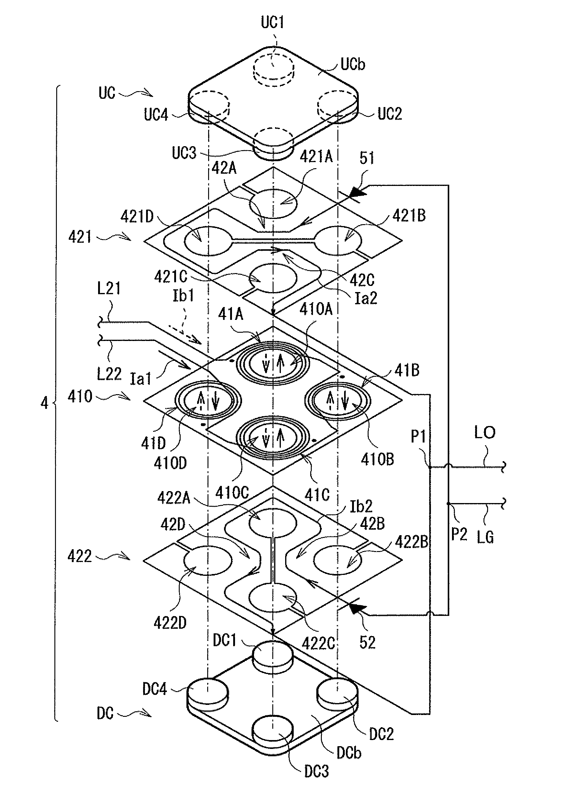
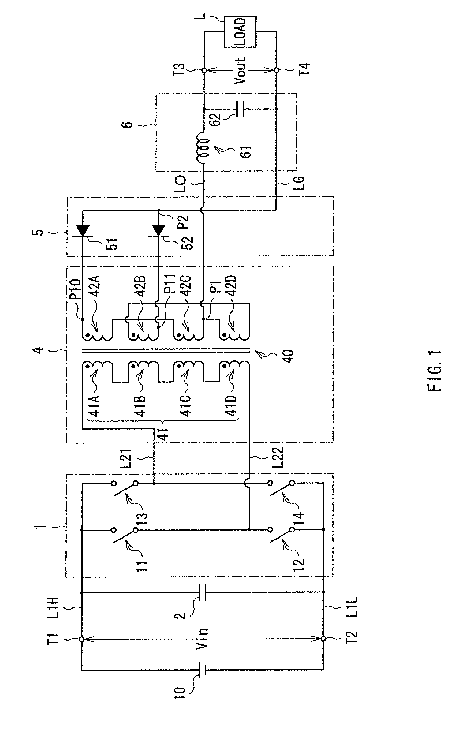
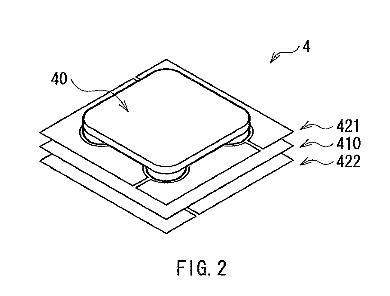
The transformer includes: a magnetic core having two base-plates and four legs; a first conductive member as a first winding, having four through-holes through which the four legs pass, respectively; and one or more second conductive members as a second winding, each having four through-holes through which the four legs pass, respectively. The first and second windings are wound around the four legs. Closed magnetic paths are formed inside the magnetic core from the four legs to the two base-plates due to currents flowing through the first or the second winding. A couple of magnetic fluxes each generated inside each of a couple of legs arranged along one diagonal line are both directed in a first direction, while another couple of magnetic fluxes each generated inside each of another couple of legs arranged along another diagonal line are both directed in a second direction opposite to the first direction.

Description

BACKGROUND OF THE INVENTION[0001]1. Field of the Invention[0002]The present invention relates to a transformer having a magnetic core and a conductive member, and a switching power supply unit provided with such transformer.[0003]2. Description of the Related Art[0004]Hitherto, various types of DC-DC converters have been proposed as a switching power supply unit and provided for practical use. Many of them are of a type in which a direct current input voltage is switched by switching operation of a switching circuit (inverter circuit) connected to a primary winding of a power converting transformer (transformer element), and the switched output (inverter output) is supplied to a secondary winding of the power converting transformer (transformer). A voltage appearing in the secondary winding in accordance with such switching operation of the switching circuit is rectified by a rectifier circuit, then the rectified voltage is converted into a direct current by a smoothing circuit and ...

Claims


Application Information

Patent Timeline
Patent Type & Authority Patents(United States)
IPC IPC(8): H01G5/00H01F27/24
CPCH01F27/2804H01F17/0013H01F27/255
Inventor NAKAHORI, WATARU
Owner TDK CORPARATION
Learn More